Apparently so. Terminology! Thank you for the clarification, you've renewed my interest.
Glad it was of use. 🙂
It's a shame the deep footprint is difficult to accommodate in the smaller "modest" sized rooms that this could actually work.
I'm afraid the depth is a requirement of the configuration. This is why I was always a mite reluctant to do larger versions (and have said so publically on a number of occasions, so no startling revelations here) -they get quite deep. I'm not sure why you've announced they only 'actually work' in modest sized spaces though. I've never said that. I suppose it depends on your definition of 'modest', but they'll do fine in larger spaces too. Not as well as a larger horn, in precisely the same way that all other things being equal, a good large speaker will do better in a large room that an equally good small[er] speaker. It's not supposed to be that, or something smaller though. It's supposed to be a box of moderate proportions. Alas, I've yet to beat the laws of physics, and all I'm trying to do is give people a variety of designs in different sizes from which they can choose if they so wish.
Super Pencil was designed to get the most Bass from the A12p in a reasonably sized box. JOAN "less bass gain" then FHXL FH family would probably benefit from corner loading, regardless even near a rear wall away from corners, that's still a significant real estate deficit to live with in anything other than a dedicated "smaller modest" size listening room.
IMO, JOAN horn is a bit of a conundrum. "Less bass gain" should allow it to be used in a modest, smallr size room as that would help mitigate overpowering the room with Bass Boom, Room Modes and Frequency Nulles. Sadly, the physical size and corner horn placement requirements make it difficult to place in a smaller modest sized room for desired performance. In a large room, you may end up having to employ a subwoofer and that's another can of worms getting away from why we want to use a wideband driver in the first place.
Apparently so. Terminology! Thank you for the clarification, you've renewed my interest.
It's a shame the deep footprint is difficult to accommodate in the smaller "modest" sized rooms that this could actually work for those of us looking for higher sensitivity easy impedance load speakers to pair with our low power SET amps.
I was speculating in the first post where I suggested the possible need for a subwoofer in a larger room, still, I never said "only" for use in small - modest sized rooms. Sorry if it read as if that is what I was alluding to.Glad it was of use. 🙂
I'm afraid the depth is a requirement of the configuration. This is why I was always a mite reluctant to do larger versions (and have said so publically on a number of occasions, so no startling revelations here) -they get quite deep. I'm not sure why you've announced they only 'actually work' in modest sized spaces though. I've never said that. I suppose it depends on your definition of 'modest', but they'll do fine in larger spaces too. Not as well as a larger horn, in precisely the same way that all other things being equal, a good large speaker will do better in a large room that an equally good small[er] speaker. It's not supposed to be that, or something smaller though. It's supposed to be a box of moderate proportions. Alas, I've yet to beat the laws of physics, and all I'm trying to do is give people a variety of designs in different sizes from which they can choose if they so wish.
Thank you for going ahead with doing the design, it is a nice option to have despite the depth and I assume that it is also easier to place than a not as deep front to back depth-wise double mouth BLH which IIRC need at least a good 10' from driver/baffle to listening position (for the 2xBLH) to come into focus.
Last edited:
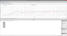
Back on topic, After reading the papers from Martin King for the first round, i tried to sim a TL with this CHN110 driver in Transmission Line from Leonard Audio and seems to get it easely to 25Hz in a 215cm long TL with a restricted end. I don't know how trustworthy this software is, but i can't get any result at all in Hornresp (mainly because it's a program that i can't learn it seems) and that mathcad file from Martin King that everybody refers to is nowhere to be found...
I don't know if you consider this a good result.
I don't know if you consider this a good result.
Attachments
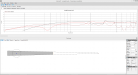
Not bad; for whatever it's worth I'd suggest looking at slightly higher tuning; as is you're looking at some losses above Fb which may rob some energy in this region, although it will likely give the driver some loading protection. You may find it easier to shift to a full MLTL or tapered (contracting) line, which should allow you the kind of tuning you want in a slightly shorter pipe; that should also help attenuate some of the unwanted higher harmonics.
Thanks Scott for your tips, i took in mind what you said and made a new version, and it already looks a lot better. Less resonance and a smaller (so cheaper) box for only a slightly higher tuning (more in the region i was aiming for wich is 30Hz). I reduced the last two sections in size and shortened the path to 1.43m. Maybe i do a testbuild for this in mdf. I'm far out of my confort zone with TL's so no birch ply builds yet, but the final version will be birch ply for sure.
Attachments

You might want to have a look at something like this (quick back-of-envelope calculation only, not a refined design -I haven't had chance to model it): 50in length, 10:1 taper, throat = 125in^2, terminus 12.5in^2. Zd = 5in. Lag the first 1/2 of pipe with 1in OC-703, SAE-F10 wool felt or equivalent. This is assuming 1/2ohm series R for typical wire, connection resistance. Fb should be 30Hz or thereabouts, probably with a very lightly damped rather than max-flat alignment.
Ive had a play with a couple of online tqwt apps, with very similar results FR around 41hz with an F3 of 21 to 25hz. Volume around 43l
a couple of online tqwt apps
I have yet to see one that gives decent results. All, so far, have been based on classic design principles (largely left behind because it works poorly).
dave
I have yet to see one that gives decent results. All, so far, have been based on classic design principles (largely left behind because it works poorly).
dave
I'm sticking with the Festivals tbh, I just find it interesting.
You might want to have a look at something like this (quick back-of-envelope calculation only, not a refined design -I haven't had chance to model it): 50in length, 10:1 taper, throat = 125in^2, terminus 12.5in^2. Zd = 5in. Lag the first 1/2 of pipe with 1in OC-703, SAE-F10 wool felt or equivalent. This is assuming 1/2ohm series R for typical wire, connection resistance. Fb should be 30Hz or thereabouts, probably with a very lightly damped rather than max-flat alignment.
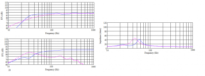
I don't think that works, tuning is to high and the resonance is a lot more. At least not with this tool of which I found out people used it with success (which does not tell everything I know). I'm still studying the math also, because I like to know that. But it's not easy matter for someone who did not study math enough at school.
But this is the response i got, or you calculated wrong, or i did not understand your instructions...
thanks btw for all the effort you put in my questions.
Attachments
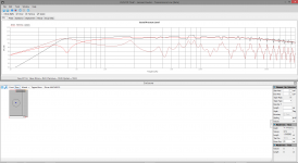
It looks OK to me (attached), so you're doing something wrong somewhere. From a quick look, you seem to have a Vb of only 13.97 litres which is far smaller than specified; this pipe should be closer to 55 litres (think a box 10in wide internal, 12 1/2in deep at the throat, 1 1/4in deep at the terminus, 50in total length, driver tapped into the pipe 5in from the throat).
If you want advice, realistically I think you're pitching for a tuning frequency a little lower than this unit will do with optimal performance. This tapered pipe should be reasonable, but I'd be inclined to review the objectives a little and perhaps modify the approach. Not necessarily massively, but a slightly more conservative tuning may work out better in the long run. If you want to push the driver as low as possible, I suggest you look at a pipe horn (like the BIB, which don't look pretty on a sim but work much better in practice) but be careful with the volume knob as the price will be power handling.
If you want advice, realistically I think you're pitching for a tuning frequency a little lower than this unit will do with optimal performance. This tapered pipe should be reasonable, but I'd be inclined to review the objectives a little and perhaps modify the approach. Not necessarily massively, but a slightly more conservative tuning may work out better in the long run. If you want to push the driver as low as possible, I suggest you look at a pipe horn (like the BIB, which don't look pretty on a sim but work much better in practice) but be careful with the volume knob as the price will be power handling.
Attachments
Last edited:
I appreciate your advice, so what kind of tuning frequency would you recommend. I've red that it can be 15hz below the resonance frequency of the driver, that is why i thought 30hz would be a good frequency. FS is 44Hz.
But i'll make some more sims, also higher in frequency.
But i'll make some more sims, also higher in frequency.
I've red that it can be 15hz below the resonance frequency
Perhaps for a specific driver. Generally one looks to a fraction of the Fs (0.707?). I never bother, my miniOnken alignment goes for finesse not max extention and i am never in danger. Scott designs all the horns & TLs.
dave
Right, your realistic vented limit is 0.707Fs or about 31.22Hz in this case, providing you are happy to trade off that for power handling; you can take it lower in something like a BIB as it's a larger, more acoustically efficient load, but we're into horn loading at that point. For a relatively simple enclosure, depending on how large you want to go, I'd probably aim for about 36Hz. Being a simple sort of soul, I like MLQWs (MLTLs), so here's one that does more or less that. You can lower Fb to 33Hz by increasing duct length to 140mm, although that's on the limit of how long a duct I prefer to use.
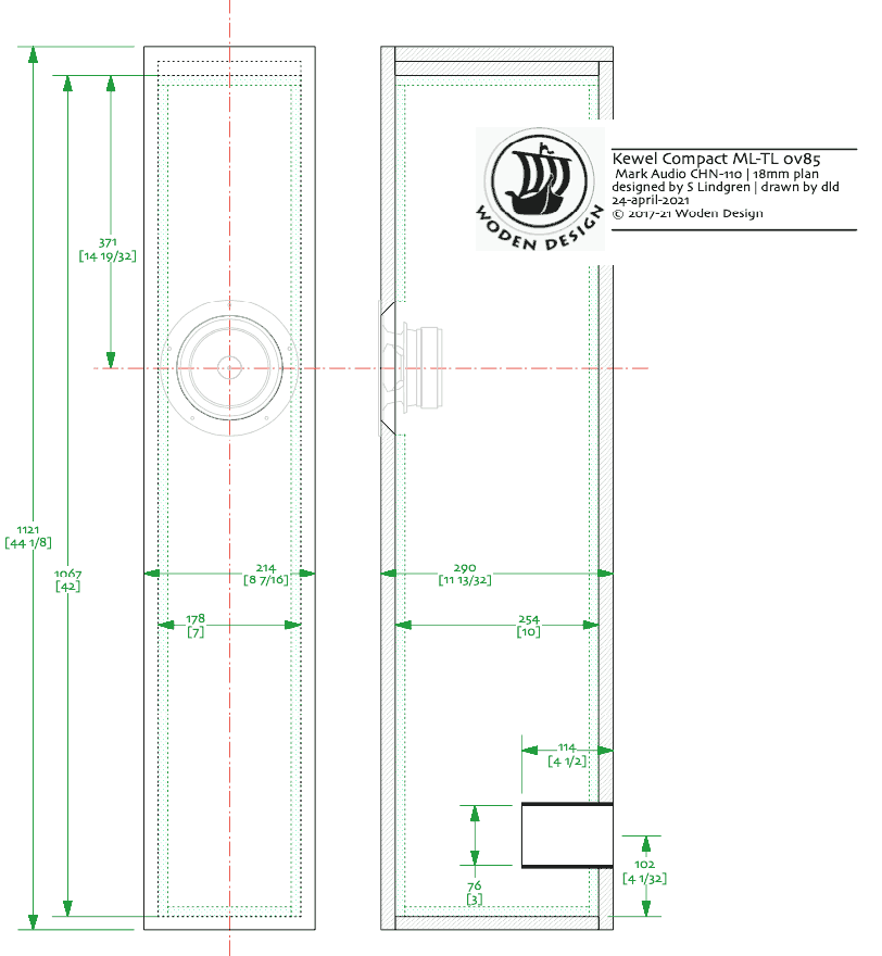
http://wodendesign.com/downloads/Kewel-compact-MLTL-CHN110-0v85-240421.pdf
http://wodendesign.com/downloads/Kewel-compact-MLTL-CHN110-0v85-240421.pdf
I don't like back ported speakers, they are to place depending. Would it be feasable to put the port on the front? For the rest i like this design but i have no id yet how to design this kind of TL.
I did do a similar design like before after your remark, but now more arround 40hz tuned. I also checked xmax limits this time (wich i did not watch before) and you're right, i was pushing it beyond it's limits of excursion.
This is tuned much higher, somewhere between 35 and 40 hz (depending on how you count it) and is a more realistic design i think. I'm now off to bed (it's 00h30 over here in Belgium), but tomorrow i'll try to sim this setup again in hornresp if I manage to find how...
Attachments
Right, your realistic vented limit is 0.707Fs or about 31.22Hz in this case, providing you are happy to trade off that for power handling; you can take it lower in something like a BIB as it's a larger, more acoustically efficient load, but we're into horn loading at that point. For a relatively simple enclosure, depending on how large you want to go, I'd probably aim for about 36Hz. Being a simple sort of soul, I like MLQWs (MLTLs), so here's one that does more or less that. You can lower Fb to 33Hz by increasing duct length to 140mm, although that's on the limit of how long a duct I prefer to use.
Actually you got me thinking, and i tried to sim your design (recreating it in my software) with very good results. Thank you for that i learned a lot with this example. I think I understand now this kind of design (but not the details yet). I'll study further on this...
Attachments
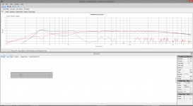
A touch under-damped in your sim as you haven't added any damping. It's deliberately a near maximally-flat alignment when trimmed out as designed so does not have any peaking at Fb. The generalarities look correct though.
The rear duct position is functional; this is part of a series of similar MA boxes I've been doing and is there to prevent any self-resonant modes in the duct becoming audible. Shouldn't be a major issue here, but it does cut down noise a touch. More generally, I've not found rear duct locations to be significantly harder to position than alternatives unless the enclosure is very close to a front boundary / boundaries.
The rear duct position is functional; this is part of a series of similar MA boxes I've been doing and is there to prevent any self-resonant modes in the duct becoming audible. Shouldn't be a major issue here, but it does cut down noise a touch. More generally, I've not found rear duct locations to be significantly harder to position than alternatives unless the enclosure is very close to a front boundary / boundaries.
Last edited:
Thanks Scott.
I did a lot of sims with all the good info you gave me and have more or less a design ready that i think may work. I learned a lot while doing that and the papers or Martin King start to make more sense to me...
But in the sims it ask damping over the whole lengt of 2 to 4kg/m³. you only damp the upper part, but when i try to sim that i have a lot more resonances. Can you explain how that works in yours?
I've red a lot about that damping and i see all kind of methods, but there is no clear winner or explenation why. I see from filling the upper half to 3/4 with fiberglas, to stuffing the whole pipe with loose whool or polyfill. That part is still very confusing for me.
I can still go both ways in my design (Someone is drawing it for me now, i can't work with cad). My design is a straight pipe 20cm wide, 30cm and 118cm long with bracing (pointed vertically). Driver is centered at 35cm from top and port is a slot (i don't like those plastic things) of 4x20cm and 8.8cm long, on the front with the bottom of the port at 8cm from the bottom of the cabinet. I'll publish plans when i have them (but that can take time, my cad-drawer does that also in free time).
A transmission line is a pipe with an exit terminus. The output of the terminus needs to be low-passed to eliminate unwanted higher frequency harmonics leaving only the fundemental to extend the reach of the LF.
Damping, Zd, mass loading are the prime ways of creating this LP function.
A traditional TL uses mostly damping to achieve this, but that almost always decrease the output of the fundemental as well as the unwanted harmonics.
In a modern TL you will often see Zd placed such that the 1st unwanted harmonic, allowing for less damping and more bass reinforcement. A mass loaded (restricted) terminus achieves similar.
A taper that decreases the cross section approching the terminus (typical tapered line) moves the unwanted harmonics up in frequency and allows for easy suppression of unwanted harmonics. and can be shorter. A line tapering the other way (Voigt) decrease the frequency at which harmons occur and needs to be longer.
Many wasy to skin the cat.
dave

I was thinking of using Rockwhool Sono Base (very similar to OC703, but basalt based fiber, not silicium based like OC703). OC703 is impossible to find here, and where it's typical used in the US, Rockwhool Sono is used here. Its sheets are 45mm thick, 35kg/m³ and are used a lot for acoustic treatment down here in music studio's and other buildings where it matters. I have specs sheets but they are in dutch...
Last edited:
- Home
- Loudspeakers
- Full Range
- The new Mark Audio CHN-110 6" driver