jleaman said:
Why would you spend and build a Mini A for a headphone amp, that does not make sense to me.
because
of this
GRollins said:When only the very best will do...
Grey
the 6moons article was pretty telling.
I want to build one of those one day.
That and a Pumpkin in one kit. Nice integrated kit right there.
That and a Pumpkin in one kit. Nice integrated kit right there.
Zen Mod said:
winslow said:I want to build one of those one day.
That and a Pumpkin in one kit. Nice integrated kit right there.
😉
that will need lots of case .........
Mounting air core inductors?
Hi again,
re my previous question re coupling, managed to figure it out.
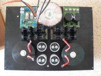
However wondering if anyone would mind taking the time to look at my layout.
Everything has been wired up since and is working fine -- although there are just a couple of things that are bugging me right now -- a high frequency buzz only detectable when volume is at max, and a very very slight hum -- again only audible when the ear next to speaker.
I suspect I may have run into an issue mentioned in the aleph-X wiki, that Magnetic fields from inductors may also be a concern, especially for air-core inductors, so give due consideration to mounting and shielding.
My diy'ed inductors (0.9mh, DCR 0.2 ohm) are enclosed next to the caps. But the tubing and cap enclosing them is aluminium. I presume that this provides inadequate or no shielding? When powered on, there is also some vibration from them, so I think I will have to damp them too (what is recommended, filling the enclosure with sand, varnish?).
Finally, the steel mounting bolt goes through the centre of the inductor. Could this cause a problem? -- I could alway change it to a plastic mounting bolt.
My rails are at about 21.7v and after an hour or so the heatsinks are 'crikey hot' (5 seconds hands on), so I may add a resistor to make the PSU a CLRC, just to drop the rails a bit more. PSU is running two channels, each biased at 2A.
thanks in advance.
Hi again,
re my previous question re coupling, managed to figure it out.
However wondering if anyone would mind taking the time to look at my layout.
Everything has been wired up since and is working fine -- although there are just a couple of things that are bugging me right now -- a high frequency buzz only detectable when volume is at max, and a very very slight hum -- again only audible when the ear next to speaker.
I suspect I may have run into an issue mentioned in the aleph-X wiki, that Magnetic fields from inductors may also be a concern, especially for air-core inductors, so give due consideration to mounting and shielding.
My diy'ed inductors (0.9mh, DCR 0.2 ohm) are enclosed next to the caps. But the tubing and cap enclosing them is aluminium. I presume that this provides inadequate or no shielding? When powered on, there is also some vibration from them, so I think I will have to damp them too (what is recommended, filling the enclosure with sand, varnish?).
Finally, the steel mounting bolt goes through the centre of the inductor. Could this cause a problem? -- I could alway change it to a plastic mounting bolt.
My rails are at about 21.7v and after an hour or so the heatsinks are 'crikey hot' (5 seconds hands on), so I may add a resistor to make the PSU a CLRC, just to drop the rails a bit more. PSU is running two channels, each biased at 2A.
thanks in advance.
Attachments
Re: Mounting air core inductors?
temporary replace chokes with resistors - if buzz is gone - there is culprit ;
same for steel bolts ; sometimes they are bad , sometimes not ; try without them and you'll know
ssmith said:Hi again,
...........
temporary replace chokes with resistors - if buzz is gone - there is culprit ;
same for steel bolts ; sometimes they are bad , sometimes not ; try without them and you'll know

The voltage is fine, but the current looks to be a little scant, particularly if you have a lower impedance load. It might be a good idea to parallel two sets of outputs, or perhaps even three.
Grey
Grey
Hello,
I'm interest in the mini A and I 'd like to know if the first diagramm (12/28/01) of GRollins is still the same...
English's not my mother language so I've some questions to ask...
How are the inputs: balanced or unbalanced?
I'm looking too for the diagramm of the power supply...
...and for the exact values of components of the amplifier for example I'can't see the watt values for resistors.
Thank you: David
Inputs are both balanced or single ended.
No diagram of the pwr supply, I think the original Mini-A called for +/- 15 volts, the Mini-A / A30 called for +/- 25-30 volts.
Most resistors are 1/4 watt, I think a few on the output side were 3 watt.
No diagram of the pwr supply, I think the original Mini-A called for +/- 15 volts, the Mini-A / A30 called for +/- 25-30 volts.
Most resistors are 1/4 watt, I think a few on the output side were 3 watt.
you can use a little CRC filters with 10000µf/40V or 15000µF/40V
for braingt pcb with balanced input you must have 15V/rails
on this web page you have all th ethinks you must know to buil d an mini a
http://diyamps.com/aleph/aleph.shtml
look at power supply page there is a parts list too
regards
fostexman
for braingt pcb with balanced input you must have 15V/rails
on this web page you have all th ethinks you must know to buil d an mini a
http://diyamps.com/aleph/aleph.shtml
look at power supply page there is a parts list too
regards
fostexman
zycomatique said:"I think a few on the output side were 3 watt."
Well I'd like to be sure!
http://diyamps.com/aleph/docs/miniALEPH-parts_list.xls
NOTICE the tabs on the bottom of the spread sheet. By default it opens to the A30 not the Mini-A.
zycomatique said:Hello,
I'm interest in the mini A and I 'd like to know if the first diagramm (12/28/01) of GRollins is still the same...
English's not my mother language so I've some questions to ask...
How are the inputs: balanced or unbalanced?
I'm looking too for the diagramm of the power supply...
...and for the exact values of components of the amplifier for example I'can't see the watt values for resistors.
Thank you: David
There's always the possibility that I'm misunderstanding, but I'll give it a try...
--Is the circuit still the same? Well, yes, in the sense that I've never gotten around to doing a Version 2.0. For a while there I almost talked myself into doing a JFET front end with either the 2SJ109 or two 2SJ74s, but it would have been counterproductive for me at the time. Nelson later published a similar circuit (one of the First Watt amps) so that's always an option. My feelings at the moment trend towards more drive current for the output stage (yes, I know the thing looks fine on paper, but I don't want to get sidetracked) and JFETs are pretty limited in the current department.
--I may be missing the point, but the Mini-A has an unbalanced front end. There's no reason you couldn't put a balanced front end on it, though.
--I never published a schematic for the power supply for the simple reason that most DIY folk use whatever comes to hand, not what I happened to use. If you look at threads here at DIY you'll find that the overwhelming majority of people use transformers they found or got from one of the surplus sites on the web. Since I have no way of knowing what other people might have in their junk boxes and the surplus sites never have the same parts two months running, it would be an exercise in futility to make a big deal out of the power supply. Basically you're looking for a transformer that will give you 12Vac or so, maybe a little more. It will need to be able to supply around an amp without overheating...call it 2A capability per channel. Then throw a decent sized bridge in and 10 or 20000uF worth of caps after that and you're pretty much ready to go. Just shoot for 15Vdc or a little over and you'll be in good shape.
--I thought the resistor wattage question had been covered, but maybe not. In any event, the Source resistors for the MOSFETs and the sense resistors at the output need to be larger--most people use the blue Panasonic 3W metal film resistors from Digikey. They're fairly cheap and work well. All the rest can be 1/4 or 1/2W as there's no appreciable heat dissipation in any of them.
Grey
Grey first of all I wanted to thank you for this little amp. I have started one but had a domestic turn and had to quit. I have since started a second for a friend and am VERY much looking forward to hearing it.
The real reason for my post is the inputs. I don't know if you are aware of BrianGT's PCB's.
At some point the PCB's designed and sold by BrianGT "developed" a balanced as well as single ended inputs. And his PCB's are really quite good, you would be proud.
Thank you again for all of your contributions here on DIYAudio, some of us less talented folk (ME) really appreciate it.
MikeW did some Mini-A boards a while back and there are others here and there.
I'm all for balanced inputs--I just didn't bother with them on the Mini-A because I wanted to keep it simple. It's not all that difficult to convert the Mini-A's front end to balanced, though.
Grey
I'm all for balanced inputs--I just didn't bother with them on the Mini-A because I wanted to keep it simple. It's not all that difficult to convert the Mini-A's front end to balanced, though.
Grey
Thanks for your help!🙂
I'd like to realize the best sounding amp as possible:
1/ I've seen on the Pass website that some people did realize their amp in wiring each element point to point instead using a pcb: did someone compare the sound of this two kind of aleph?
At your sense wich gauge do I have to use to wire such an amp?
2/About the power supply capacitors: I read lot of times that using a cap with the lowest possible resistance was good and that using a lot of little caps instead of a big one did increase once again the sound quality. Do you agree with it in the case of the mini A?
- Home
- Amplifiers
- Pass Labs
- The Mini-A