describe tests
I resume that these graphs are with OS, but can't be sure from your explanation
just in case - to measure anything in this context, you must do it proper - balanced
so, bal output from soundcard, bal amplification, bal signal back to soundcard
and remember - balanced/differential is always going to cancel even harmonics ...... more or less; and that more or less must be measure of your doing
which means - take one setup as reference, sim and measure;
change something, sim , measure
try more, choose what suits you most
In post 109 I shown the thd at 190hz and 1khz for the output stage at ~2v(1w) into my speakers. I used balanced signal from my preamp.
In one test I used Iron Pre and in the other a balanced ba3 front end, I can swap the gain pcbs in my preamp.
In post 120 I did the ffts to see the thd of the preamp at 1khz only, first attachment is IP second is bba3.
In one test I used Iron Pre and in the other a balanced ba3 front end, I can swap the gain pcbs in my preamp.
In post 120 I did the ffts to see the thd of the preamp at 1khz only, first attachment is IP second is bba3.
OK, now I know more
few comments:
use 1Khz as reference when thinking and measuring THD Spectra; it is informative having data for other frequencies, but 1KHz is sorta standard and everything else you can see from THD vs. Frequency graph (showing 2nd, 3rd, 4th in Freq. domain)
again, you can expect, more or less, that FE is going to be dominant for resulting THD Spectra of FE+OS combo
whatever, we can contemplate all day long, measurements will show what's reality
edit: what's real difference of using IRFP150 instead of IRFP240 - you can first predict using sim, and after that with actual change in am itself - making measurements of both iterations
in general, when speaking of non bridged stages - if you place part with higher xconductance in lower rail, there is increase of 2nd, negative
if you place part with higher xconductance in upper rail, there is increase of 2nd, positive
same way - if you place part with decreased xconductance (bleak lateral ...... or SIT or Schaded mosfet) in upper rail, increase of 2nd, negative
if you place part with decreased xconductance in lower rail (bleak lateral of Schaded mosfet), increase of 2nd positive
now, what is happening in bridged configuration - match of several factors, FE included, and no use of too much predictions in general, better to work on particular case and voice it according to one's wishes
few comments:
use 1Khz as reference when thinking and measuring THD Spectra; it is informative having data for other frequencies, but 1KHz is sorta standard and everything else you can see from THD vs. Frequency graph (showing 2nd, 3rd, 4th in Freq. domain)
again, you can expect, more or less, that FE is going to be dominant for resulting THD Spectra of FE+OS combo
whatever, we can contemplate all day long, measurements will show what's reality
edit: what's real difference of using IRFP150 instead of IRFP240 - you can first predict using sim, and after that with actual change in am itself - making measurements of both iterations
in general, when speaking of non bridged stages - if you place part with higher xconductance in lower rail, there is increase of 2nd, negative
if you place part with higher xconductance in upper rail, there is increase of 2nd, positive
same way - if you place part with decreased xconductance (bleak lateral ...... or SIT
or Schaded mosfet) in upper rail, increase of 2nd, negativeif you place part with decreased xconductance in lower rail (bleak lateral of Schaded mosfet), increase of 2nd positive
now, what is happening in bridged configuration - match of several factors, FE included, and no use of too much predictions in general, better to work on particular case and voice it according to one's wishes
Last edited:
I used 190hz to have a reference at the minimum load the amp will see.use 1Khz as reference
My amp is situated in this category but has the part with the higher transconductance in the negative phase. Is it correct to say that the 2nd of the entire amp is negative?if you place part with higher xconductance in upper rail, there is increase of 2nd, positive
Looking also in the simulation I see that by connecting the irfp150 like I have it now(on the neg phase) I get 3x higher thd than with the irfp240.
The simulations for both of the above combinations show negative numbers for the phase of the harmonics.
If the thd is lower with irfp240 and also the negative 2nd is predominant I guess I could go with this one or my understanding of the sims and entire thing is wrong?
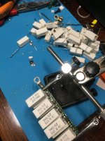
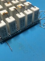
Yesterday night I disassembled a few current sensing resistors that I had around. I got a few 0.1r wirewound resistors which I will use to build a dummy load(3.5-4r) and most probable I will use some also in the power supplies to adjust the crc filters which will become rcrc.
edit: added the screenshots for the 2 simulations, 1st is with irfp150 and second with irfp240
Attachments

Last edited:
Thanks
Trying to simulate I get an error that I miss the models for the semis. How can I add those?
Trying to simulate I get an error that I miss the models for the semis. How can I add those?
I will try later tonight to replace the models.
I just finished soldering my dummy load. I have also fine tuning between 3.5-4ohm 😎
I just finished soldering my dummy load. I have also fine tuning between 3.5-4ohm 😎
Attachments
I gave another try to the sim with the library replaced but still nothing.
I copied the models from Cordell website and included the txt file into the sim. Like this it works half way because it still misses the models for the bjts.
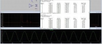
I connected the 4 ohm load to the amp. It warms up a bit at 10w dissipation.
I can get ~12w @ 1% thd, the screenshot went bad so I need to repeat the test.
The attached one is for 1w
I copied the models from Cordell website and included the txt file into the sim. Like this it works half way because it still misses the models for the bjts.
I connected the 4 ohm load to the amp. It warms up a bit at 10w dissipation.
I can get ~12w @ 1% thd, the screenshot went bad so I need to repeat the test.
The attached one is for 1w
Attachments
replace bjts too from your LTSpice library
practically any general purpose type TO92 will work, both in sim and in actual circuit
dunno what system you have in your comp, but under winshit , LTSpice is having libraries in two places - Program Files and in My Documents
practically any general purpose type TO92 will work, both in sim and in actual circuit
dunno what system you have in your comp, but under winshit , LTSpice is having libraries in two places - Program Files and in My Documents
most likely you have Spice directory somewhere else too
search for info
I'm still on W7, due to several programs I use and they're getting finicky under W10
edit: standard.bjt too
editedit - reuploaded proper file
search for info
I'm still on W7, due to several programs I use and they're getting finicky under W10
edit: standard.bjt too
editedit - reuploaded proper file
Attachments
Last edited:
Yes
I managed to start the sim. The trick was to add the libraries to my documents.
What is E1 and E2 ? For what are these used?
I managed to start the sim. The trick was to add the libraries to my documents.
What is E1 and E2 ? For what are these used?
click probe on it's poles and you'll see
first one is nothing else than inverter, second one is bal to se converter
hover with mouse on it,ctrl+rightclick gives you table of settings
first one is nothing else than inverter, second one is bal to se converter
hover with mouse on it,ctrl+rightclick gives you table of settings
🤔 Nice feature, I didn’t work with this one yet.
I am waiting for the isolators now so I can play a bit with the bias.
I am curious how it sounds at 1.5-1.6a bias/fet like the aleph was.
I am waiting for the isolators now so I can play a bit with the bias.
I am curious how it sounds at 1.5-1.6a bias/fet like the aleph was.
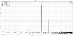
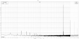
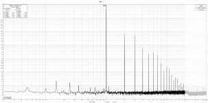
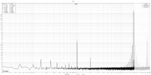
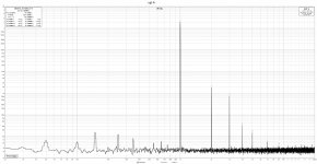
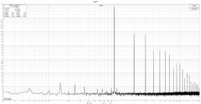
Today I replaced the bba3 gain stage(actually it is a muscle bba3, it has buffers on the input and output and also global feedback) in my preamp with Iron Pre(also a muscle version with the output buffered) and repeated the measurements I did yesterday.
1st screenshot is the thd @ 1w/1k, 2nd is the thd @ 1w/10k, 3rd is the thd @ 14w/1k, 4th is the imd @ 1w/19&20k.
Not much difference between one gain stage and the other.
Searching a bit in the old folders on my pc I found that the the aleph(heavily biased(1.6a/mosfet) as I had it) did 1% thd into 4ohm at the same 7.6Vrms as boo does, only that boo is doing it this with close to half of the aleph bias. Nice! and thanks again ZM
Attachments


- Home
- Amplifiers
- Pass Labs
- The marriage