
Did you just Babelfish the M2 again?
View attachment 1102654
Except this time it's the Babelfish M2 OS (PoP version) with the M2 FE ... but it's a completely different amp (because it's missing the jfet buffer)
Cheers,
Stephen
it already happened to me in reality** - literally completing paper part of project of same amp , twice in 10 days
and when I realized it, comparison did show that I made it with irrelevant difference between original and next Groundhog Day
**mine is really tricky one; luckily I stopped fighting and being surprised;
choose:
Attachments


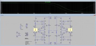
Yesterday I had a bit of spare time and put together the asc file for the boo to understand better how it works/performs.
First thing that I did was a thd sim and after that I did an output impedance sim.
For the output impedance I got a very high value. What I am doing wrong that I get this high value?
First thing that I did was a thd sim and after that I did an output impedance sim.
For the output impedance I got a very high value. What I am doing wrong that I get this high value?
Attachments
can't tell, don't care for Rout, because I know it is much lower than if you have source resistors
though, I believe ( if I interpret your formula properly) there is an error - you need to compute it as Rout = DeltaU/DeltaI
and for that sim, you can use just one phase/half, with 4R load as base
anyhow, with Cordell's 240/9240 models, I just got 0R13 per phase
double that for bridge - 0R26
means damping factor 8R/0R26=30
not bad for no-FB construction
I do the calculation as you say: (V(o+)-V(o-))/I(V6).you need to compute it as Rout = DeltaU/DeltaI
V(o+) is the voltage at node o+ which is positive output
V(o-) is the voltage at node o- which is negative output
I(V6) is the current that goes through the voltage source that I use to measure the output impedance.
With 4r as base you mean having the load connected?
I still need to learn how to play with new models, it will be soon.
So into 4ohm I am getting something like 15df(4/0.26) with the boo and was getting 10(4/0.4) with the aleph j.
A very nice improvement that I felt from the first tracks that I listened.
no need for overcomplication
Case 1 - run sim for nominal load; read voltage across load, read current through load, write down both
Case 2 - run sim for (say) 50R as load; read voltage across load, read current through load, write down both
then Rout=DeltaU/DeltaI
where Delta is (Case1 - Case2)
Case 1 - run sim for nominal load; read voltage across load, read current through load, write down both
Case 2 - run sim for (say) 50R as load; read voltage across load, read current through load, write down both
then Rout=DeltaU/DeltaI
where Delta is (Case1 - Case2)
and - I believe there is not much to hear as difference between DF 10 and DF 15 ....... what you hear as difference is more result of completely different concepts of these two amps, and what you like more is completely up to your personal preferences
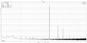
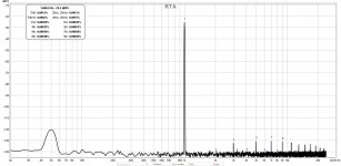
This time I went for something more realistic.
I chosen 190hz because my speakers get to 3.4ohm at this frequency being 4ohm nominal. I did the measurements directly with the speaker as load.
The bias was 1amp.
To see if the thd profile changes I used 2 different line stages. Iron Pre was one which is UGT in the description of the photo, the other one is a bba3 and is named UGX in the description.
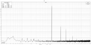
Attachments
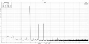

I didn’t replace the aleph because it wasn’t sounding good but because for the power levels that I need now it wasn’t very efficient.what you like more is completely up to your personal preferences
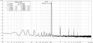
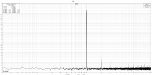
I am attaching an fft for the aleph output on the same load as boo
Attachments
you owe us more porn, amps in system
OK, we've seen most interesting - guts - but there is also importance of overall visual impact
made red dots change?
OK, we've seen most interesting - guts - but there is also importance of overall visual impact
made red dots change?
Not yet, most probably I will drill the holes in the weekend or the next week.
I turned on only one channel for a few minutes to do the ffts.
I will share a few photos once I put the preamp in an enclosure.
I turned on only one channel for a few minutes to do the ffts.
I will share a few photos once I put the preamp in an enclosure.
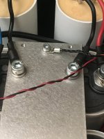
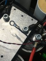
Today I had a bit of courage and moved the small signal gnd.
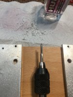
I am still waiting for the isolator sheet and (for a week now )I am searching also for a used torque screwdriver. Not much to find around.
When doing it only with your hands, how can you know that you tighten enough? For 1nm you need to apply ~100g of force.
What happens if you over tighten ?
I am still waiting for the isolator sheet and (for a week now )I am searching also for a used torque screwdriver. Not much to find around.
When doing it only with your hands, how can you know that you tighten enough? For 1nm you need to apply ~100g of force.
What happens if you over tighten ?
Attachments
-
 71BE92B0-FFEB-4F1D-ADFC-69715B2DB604.jpeg375.2 KB · Views: 93
 -
 8F13363F-D194-4449-B554-BF7A936444DC.jpeg485.2 KB · Views: 88
 -
 374E120C-79FA-4579-BC97-DB2CEC5DE018.jpeg376.7 KB · Views: 93
 -
 BFDE1099-49B6-42FA-9B45-0C04ACCEAC51.jpeg589.2 KB · Views: 88
 -
 952C1943-22A8-47E1-81FE-C042A478F2DA.jpeg346.1 KB · Views: 88
 -
 0D34B2BA-9F1D-4AE5-9544-7854AC54C889.jpeg547.5 KB · Views: 99
if you overtighten on Keratherm, it'll just sink more on screw side
I mean, not critical at all, but me just being anal about torque screwdriver, perfect way of not thinking anymore about that issue
nice to have, but not necessary for DIY amount of work
I mean, not critical at all, but me just being anal about torque screwdriver, perfect way of not thinking anymore about that issue
nice to have, but not necessary for DIY amount of work
I am more on this side. For now I don’t have so many amp pcbs to replace inside the enclosures so I will take my chances with a kitchen scale to make an idea how much force I need to apply.nice to have, but not necessary for DIY amount of work
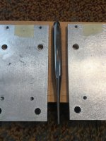
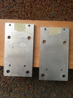
Today when I searched for the oil(to make the threads in the holes) I found some rc bullet connectors.
The females could be soldered perpendicular to the pcb and the males on the wire giving a very simple way to replace the amp pcb.
For small currents 2mm is ok and for big currents 5mm. Never seen someone using them in an amp and I was thinking to solder a few on my pcbs to give them a try.
Attachments

I am curious about a thing or to put it another way I don’t understand it😎
If I add a front end and apply global feedback, the thd character of the output stage will change and be similar to that of the fe?
If I add a front end and apply global feedback, the thd character of the output stage will change and be similar to that of the fe?
I am attaching the ffts for both front ends that I used in my previous test.
One of them is h2 dominant but the other one isn’t.
In the test I got the same thd profile for both.
Could it be that I used the irfp150 on the negative phase and this changes the things?
One of them is h2 dominant but the other one isn’t.
In the test I got the same thd profile for both.
Could it be that I used the irfp150 on the negative phase and this changes the things?
Attachments
- Home
- Amplifiers
- Pass Labs
- The marriage