Now that you told me, the differences are obvious but to be honest this morning couldn’t spot a difference 🤓
When I use the pcbs bridged I need only a small gnd pad on the pcb, correct??
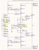
edit: I need one small wire that comes from the ps and goes to gnd on the pcb and also the gnd from the input goes to the pcb so 2 pads are needed. I attached also the copied schematic
When I use the pcbs bridged I need only a small gnd pad on the pcb, correct??
edit: I need one small wire that comes from the ps and goes to gnd on the pcb and also the gnd from the input goes to the pcb so 2 pads are needed. I attached also the copied schematic
Attachments
Last edited:

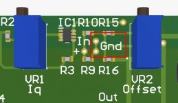
Why do you use 120r resistors in series with the zeners around the ccs and not 100r ?
For the ccs can I use same bc846a smd instead of bc546?
For the ccs can I use same bc846a smd instead of bc546?
CCS, series zeners are there to shave effective DC voltage from chip, thus decreasing dissipation, it can be only better for stability
yes, for LM 334 you can use whatever bjt you want, taking care of dissipation of part - that's why I used TO92 part, which is also easier to solder than smd; pcb size already being defined with other things and I'm using smd only when space is scarce
series resistors in series to CCS chip - antioscillation measures - damping anything called stray in connected traces
edit - why 120R and not 100R
dunno, irrelevant difference, mood reasons
naah, Mighty ZM is not having moods, ZM is having State of Inspiration
Last edited:
while I'm in Office .....
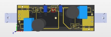
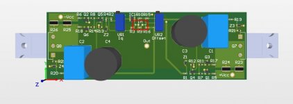
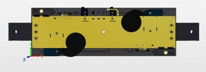
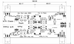
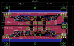
@twitchie asked for Pooh gerber files
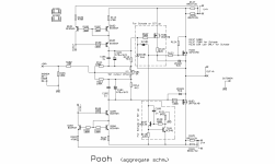
here it is (error around ZD103 taken care of) , everything in jumble; reminder - CCS Daughterboards - posts #7 and #8
enjoy!
Attachments
All clear now, thanks.
What would the schade feedback do in this case if implemented?
see Babelfish M25 for comparison
you have graphs and everything, besides Folk Tales and usual Audio Mythology
Now that you told me, the differences are obvious but to be honest this morning couldn’t spot a difference 🤓
When I use the pcbs bridged I need only a small gnd pad on the pcb, correct??
edit: I need one small wire that comes from the ps and goes to gnd on the pcb and also the gnd from the input goes to the pcb so 2 pads are needed. I attached also the copied schematic
in case of bridged arrangement, GND itself is outa energy path of amp itself, while still serving as reference and also as current return for few parts of circuit - it is involved in function of T101 (ring of two CCS)
edited post #24, 120R explained
Why do you use 120r resistors in series with the zeners around the ccs and not 100r ?
For the ccs can I use same bc846a smd instead of bc546?
if you're asking about LM334 CCS, then it is BC556 or BC856
if you're asking about small CCS glued to negative rail, serving fro Schade circuit operation, then yes - use either BC546 or BC846
dissipation is ..... nuttin'
You’re gonna have to let me know if you want any of these in your ‘list of projects’. I can’t keep up 😀
@twitchie asked for Pooh gerber files
here it is (error around ZD103 taken care of) , everything in jumble; reminder - CCS Daughterboards - posts #7 and #8
enjoy!


Thank you Mighty One!
Cheers

I was asking about the schade ccs and the resistors that are in series with the diodes on the 3092 ccs.
All clear now about that.
Now what is a bit unclear is the schade operation. When used bridge wouldn’t the effect cancel out?
All clear now about that.
Now what is a bit unclear is the schade operation. When used bridge wouldn’t the effect cancel out?
The idea of shade operation is to have a more luscious sound signature because of the negative phase second harmonic. Bridge operation will tend to cancel out almost all of the even harmonics leading to a very different sound signature; I am guessing it would be more authoritative (depending on speakers) but not as lush.I was asking about the schade ccs and the resistors that are in series with the diodes on the 3092 ccs.
All clear now about that.
Now what is a bit unclear is the schade operation. When used bridge wouldn’t the effect cancel out?
Schade is possibility
How you're going to use it depends only of you and what outcome is going to be, stays to be determined
there are always ways to shape sum output THD Spectra, as I succeeded in https://www.diyaudio.com/community/...hatever-aleph-x-servo-for-greedy-boyz.318319/
in this case, just from top of my head, it can be done having unequal Schade "amount" in two phases
as is, you will most likely use Boo and Pooh without NFB loop, so amp is not going to be SUSY, in which case whatever you do with halves is not going to be diminished with NFB action
edit: yes, of course, even harmonics are going to be nulled due to bridged/antiphase OS arrangement, but - as said - if you unbalance two halves deliberately, total nulling is impossible
Last edited:
This sounds good, can one insert a trimmer in series with the Schade resistor to adjust the thd profile on the fly?if you unbalance two halves deliberately, total nulling is impossible
probably yes, but I'm finding much better approach of having socket pins for these two resistors, so swapping them is easy, of course while amp is powered off
there is not that much leeway in value of Schade resistors, meaning differences are going to be dramatic with slight changes in values/ratio of two resistors and there are value combinations which are no-no, THD wise and stability wise
according to sims and measurements, I did found just two value combos I like - sorta standard 1K+10K, and 750R+18K
there are certainly few more possible value combos, but I'm lazy by nature, so it stays as that
NB - each altering of Schade resistor values will not alter Iq setting ( Iq biasing circ compensating change) but you'll need to re-set DC Offset for sure
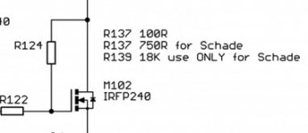
So to have a bit of negative second I should use on the positive phase 1k + 10k and on the negative phase 750r + 18kaccording to sims and measurements, I did found just two value combos I like - sorta standard 1K+10K, and 750R+18K
- Home
- Amplifiers
- Pass Labs
- The marriage