yes, you can try that
if you like it, use it........ in the end - make it as you like it more
there are various ways to alter THD Spectra; one of them - if staying at pure MOS approach - use IRFP240 in one phase and IRFP150 in second phase, as N Channel Mosfet
IRFP150 practically being 2 pcs of IRFP240 in parallel, thus doubled xconductance
regarding resulting phase of dominant - using different part in left or right side - you can check what you like more simply swapping speaker polarity
as Pa taught us - with that you're swapping polarity of dominant harmonic too
anyway - make amp, then experimemnt
Many thanks, I added the irfp150 to the basket and will proceed with the order to be sure I get all the parts.
I am adding also Schade to the pcb but unfortunately the dn2540 is out of stock till next year. Guess I will experiment with irfp150 untill then.
I am adding also Schade to the pcb but unfortunately the dn2540 is out of stock till next year. Guess I will experiment with irfp150 untill then.
Attachments

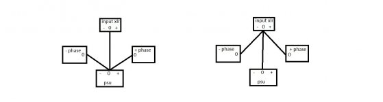
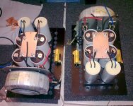
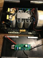
In the power supply of each monoblock(Aleph J now) I use as gnd a rectangular piece of 5mm aluminium. I suppose that from here(the rectangular piece of alu) I should go with a small wire and connect everything like in the right side of the attachment?
Attachments
😂so, you'll need new holes
Good one.
Most probable in the future I will sell the actual monoblocks with the js inside and buy with the money some cases that are already drilled and use for the future projects. It’s a dream of mine to have 4 enclosures and keep everything separate.
With an amp like this(with 0.7a bias and lower rails) 2u or 3u cases can go well.
I have ordered the pcbs and will have them in a few weeks.
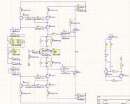
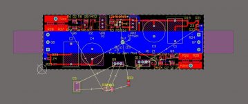
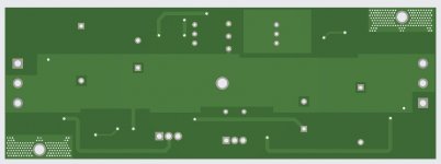
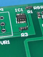
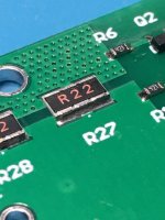
The distance between the mosfet holes is 150mm but it can be easily used with 160mm holes distance by bending the pins of each mosfet 5mm lower, the pcb will be a bit lower also.
For a single bridged channel you need 2x bom , for 2 bridged channels you need 4x bom. It still needs the Schade resistors(1k+10k or 750r+18k) to be added(0603 smd) though it contains the rest of the components for Schade.
Edit: Actually the bom has the 10k Schade resistor
Attachments
Last edited:

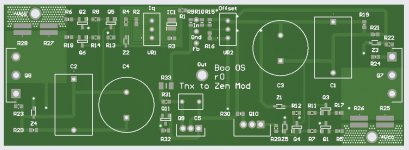
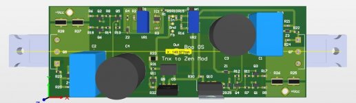
I see one mistake - note "tnx to Zen Mod" needs to be "tnx to ZM who tnx to Pa"

and - it seems you made Pooh pcb, not Boo
while we at semantics
If the pcbs wouldn’t be in production I would gladly modify them.I see one mistake - note "tnx to Zen Mod" needs to be "tnx to ZM who tnx to Pa"
I named the pcb Boo because I like the name more.
If I would remove the resistor from the crc filter in the power supply what would you recommend to put there, a cap multiplier or a voltage regulator?
call it whatever you want, names are just fun - I'm already in eternally confused state, so names are just futile try to differentiate between iterations
I prefer CLC to CRC, when I have a space for chokes in case
I also prefer cap multi to voltage reg, for that purpose
depending how much voltage you want to shave/sacrifice - use either mosfet (approx 4V drop, depending what you're going to use ; less if you use so called TTL driven mosfets so Ugs lower, but catch is finding P channel ones), or use darlingtons (around 1V3 voltage drop)
your choice
I think this is all for today. I will finish the rest tomorrow.
Attachments
-
 36F7AAD0-C586-4E9C-BC1B-2A7474F7B8AC.jpeg490.5 KB · Views: 174
 -
 88A76C39-6820-4C81-BBFD-CB6F5B175FA3.jpeg427.8 KB · Views: 176
 -
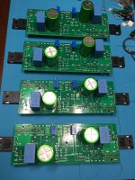 ABB61BF5-CDE6-4C41-92D7-C2B776799294.jpeg503.3 KB · Views: 179
 -
 3633EB18-BEAB-40F0-8E72-27EA9F7C44A3.jpeg245.6 KB · Views: 171
 -
 E0E7ADCD-651C-4777-81CC-4BD15867CFE6.jpeg251.6 KB · Views: 165

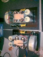
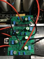
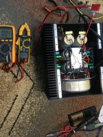
I started with the first channel by connecting each phase at a time to the ps, adjusting the bias and absolute offset.
I ended by connecting both phases and adjusting the relative offset.
I went with 1a bias for each phase, measured across the 0.5r resistors in the crc filter.
On the positive phase I went with 240 and on the negative with 150.
I ended by connecting both phases and adjusting the relative offset.
I went with 1a bias for each phase, measured across the 0.5r resistors in the crc filter.
On the positive phase I went with 240 and on the negative with 150.
Attachments
too much for my liking, really never using more than 0R1I have a 0.5r resistor in the ps crc. Can this be problematic for this amp?
I started with the first channel by connecting each phase at a time to the ps, adjusting the bias and absolute offset.
I ended by connecting both phases and adjusting the relative offset.
I went with 1a bias for each phase, measured across the 0.5r resistors in the crc filter.
On the positive phase I went with 240 and on the negative with 150.
it would be better to make it in cleanest ( identical) way at first, as reference
I finished also the second channel, now they both sing.
The same 1v across the speaker now seems to have a bit more control.
Will do some measurements the next days. I waited years for this to happen 🙂
Thank you again @Zen Mod !
The same 1v across the speaker now seems to have a bit more control.
Will do some measurements the next days. I waited years for this to happen 🙂
Thank you again @Zen Mod !
Attachments

- Home
- Amplifiers
- Pass Labs
- The marriage