Here is another take on this:
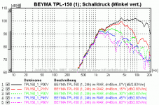
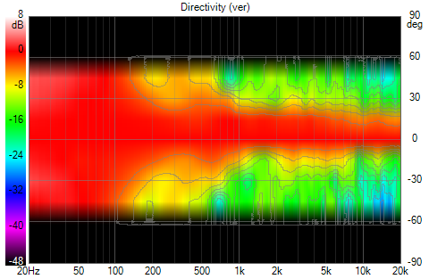
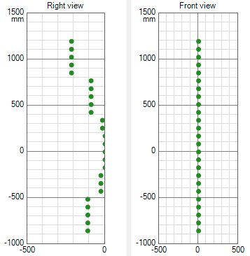
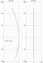
As you see, the TLP-150 is placed in the middle point between floor and ceiling, that is 241.5 mm above listening axis. The seated listening position (100 cm above floor) is therefore about 4.6 degrees below axis. Standing up is about 10.5 degrees above axis.
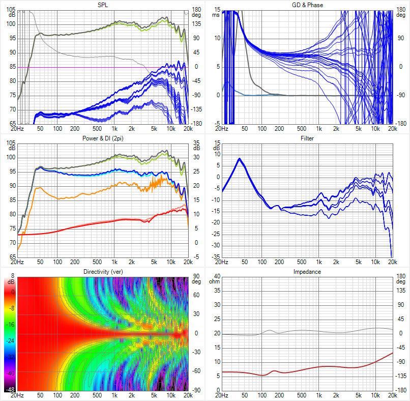
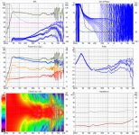
A dramatic increase of directivity in the last octave, but I think its looking quite good before that. The phase eq:s improves the dispersion in the 2-10kHz range. A comparison with and without phase eq:s:
With phase EQ:s:
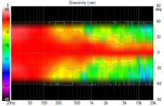
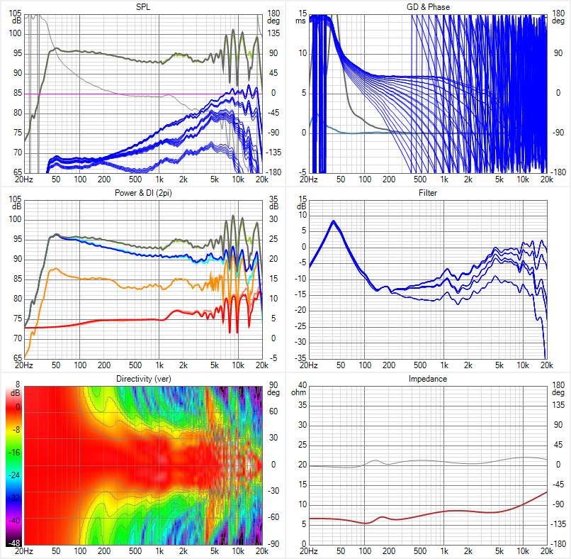
Phase EQ:s disabled:

As you see, the TLP-150 is placed in the middle point between floor and ceiling, that is 241.5 mm above listening axis. The seated listening position (100 cm above floor) is therefore about 4.6 degrees below axis. Standing up is about 10.5 degrees above axis.
A dramatic increase of directivity in the last octave, but I think its looking quite good before that. The phase eq:s improves the dispersion in the 2-10kHz range. A comparison with and without phase eq:s:
With phase EQ:s:
Phase EQ:s disabled:
Attachments


A couple of questions if I may, what does the horizontal directivity look like?
And what is the absorption of the room 's floor and ceiling set to?
Last question for now, is this plot with toe in of the speaker?
In your shoes I'd plot all angles of interest and all heights with keeping in mind a slight up/down movement (or different sized family members), to check the in room prediction. For that you need to move the driver stack and modify floor and ceiling height to vary the in-room prediction for vertical positions.
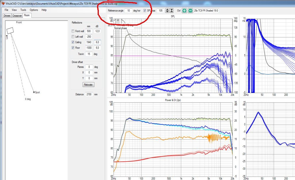
Horizontal angle is just typing in a different reference angle.
I ask for the horizontal directivity plot, as the vertical plot doesn't give me the clues why there is such a sudden change in the DI index or Power Response.
I use the speaker with 15 degree toe-in and have set my reference angle at 10 degrees. above that. I do this because moving off axis (with the left ear) to the right side would only mean moving slightly beyond that 10 degree reference angle.
The right ear, that is listening to the right speaker, would move far more in degrees respectively. This is because my microphone position is slightly in front of the couch, with the seated positions for more than one listener I place them on that couch 🙂.
Drawing it all out on a napkin with an averaged size head should help make sense of it.
And what is the absorption of the room 's floor and ceiling set to?
Last question for now, is this plot with toe in of the speaker?
In your shoes I'd plot all angles of interest and all heights with keeping in mind a slight up/down movement (or different sized family members), to check the in room prediction. For that you need to move the driver stack and modify floor and ceiling height to vary the in-room prediction for vertical positions.
Horizontal angle is just typing in a different reference angle.
I ask for the horizontal directivity plot, as the vertical plot doesn't give me the clues why there is such a sudden change in the DI index or Power Response.
I use the speaker with 15 degree toe-in and have set my reference angle at 10 degrees. above that. I do this because moving off axis (with the left ear) to the right side would only mean moving slightly beyond that 10 degree reference angle.
The right ear, that is listening to the right speaker, would move far more in degrees respectively. This is because my microphone position is slightly in front of the couch, with the seated positions for more than one listener I place them on that couch 🙂.
Drawing it all out on a napkin with an averaged size head should help make sense of it.
Last edited:
Speaking of long ribbons, Newform Research makes them .75" wide, 30" tall. I'm working on a model now....
Hi,
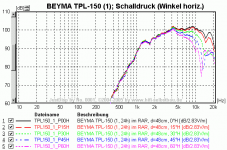
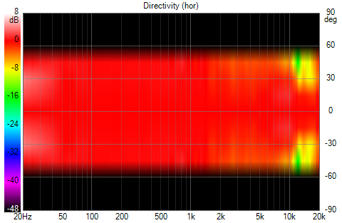
Here's the horizontal directivity:
And here is the settings in the Room tab:
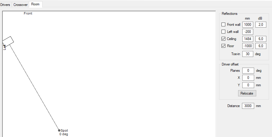
Haven't played so much with those settings, but ceiling and floor absorption is set to 6 dB. The toe-in was set to 30 deg. How do you set the reference angle? I tries changing the "User hor" in Options, but nothing happened?
I will try moving the stack and floor/ceiling heights to get those responses!
Thanks for helping me out! 🙂
Here's the horizontal directivity:
And here is the settings in the Room tab:
Haven't played so much with those settings, but ceiling and floor absorption is set to 6 dB. The toe-in was set to 30 deg. How do you set the reference angle? I tries changing the "User hor" in Options, but nothing happened?
I will try moving the stack and floor/ceiling heights to get those responses!
Thanks for helping me out! 🙂
Attachments


Reference angle is mentioned above the graphs,
If you want to move the listening plane higher, you need to lower all drivers.
For instance: Driver offset Y would be -300, in your room the floor would be -1300 and ceiling 1184.
The graphics in bottom left should change to represent that change. If you have that height of interest, you can export it to be able to load it into REW for further research etc. File -> Export -> In-room Response
It won't have phase or an actual IR, just the frequency curve is exported.
That way you can see if it lives up to your expectations.
Attachments
Speaking of long ribbons, Newform Research makes them .75" wide, 30" tall. I'm working on a model now....
Not much info on their site... so the R15 is 15" and the R30 is two of them making it 30"?
I remember lots of people running the Bohlender Graebener RD75 etc. but most of them experienced quite a few problems. I have PM-ed with a TC9 array owner who went that route and never got it to sound quite as good as that simple line of TC9's. He didn't post publicly about it so I will withhold his handle.
I hope quality control is better on these, it should be fun what one can do with it. Hope to find more info than their rather uninspiring online spec sheet.
Attachments
I tried getting off axis measurements from the supplier but no dice. Just what was on the datasheet which was on axis only.
Newform offers a 30" ribbon, the R45. I was seriously considering them when I decided to go with full range drivers instead. I'm just about to post vituix sims on the R45 in my thread.
I'm hoping to see more about them than what they present out on their website.
Your sims show that it's not going to be that easy getting a consistent wide coverage vertically.
For now I'll be sticking to "working with what I've got", what seems to be working quite well so far.
Your sims show that it's not going to be that easy getting a consistent wide coverage vertically.
For now I'll be sticking to "working with what I've got", what seems to be working quite well so far.
I don't think continuous ribbons are immune from delta path length FR ripple and when that is EQed away, there is a position dependency, very much like with discrete array except now there is less ability to shade.
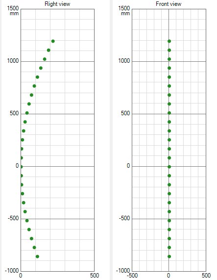
Just for fun I wanted to see what the output would look like if I added delay to the groups above and below the central drivers.
I didn't re-EQ, but the plot looks like this:
See how small the vertical directivity gets? Awesome!
Here's the driver placement. What I did is move back each group based on the largest difference in distance between it and the central driver.
(basically doubling it's delay, to move it back from the leading group, I could try it both ways, making it a more focused assay as well)
The result at the exact sweetspot would be awesome! You can see how the in room plot follows the EQ, so it can be perfectly flat without floor and ceiling influence messing it up all that much. (they are on at -6 dB each)
But the bad news: it doesn't hold up if we move up or down...
I could make it a completely bend CBT, individually moving each driver. But ideally it would also mean moving the unshaded group to the bottom for it to resemble the CBT as we know it.
Attachments

Last edited:
Actually, the above post is the focused array...
I was just misreading the driver plot in Vituixcad. So that's the result of a focused array...
The following is a CBT like array:
Using the same numbers as before, but now on a driver by driver base.
The driver placement results in:
See how it widens the directivity below 4 KHz? The top end is beyond rescue though. Not much I can think of to save that!
Attachments
So I better post one more, once again, the focused array, this time on a driver by driver base:

And the driver model:
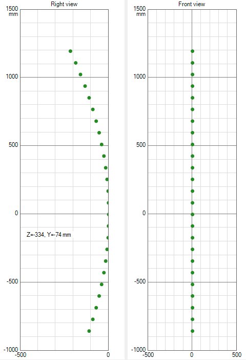
That would be an option for a fine sweet spot 🙂. The first sim posted with the groups of drivers delayed seems better in some regards,
if we can believe it's DI plot, this one is cleaner though. The shading of the groups still is what I chose for my straight optimized array.
So shading groups of drivers, hence the little differences in these plots.
If you can live with a ~10 cm vertical sweet spot... the focused array might be a valid solution 😉.
Note: for the last two sims, the floor and ceiling reflections are set to on and they flipped back to -12 dB, so take it as is.
This is just me satisfying my curiosity here.
That's it for today though...
Maybe I'll do a proper ground plane CBT out of curiosity as well. Just to have seen it in raw shape.
And the driver model:
That would be an option for a fine sweet spot 🙂. The first sim posted with the groups of drivers delayed seems better in some regards,
if we can believe it's DI plot, this one is cleaner though. The shading of the groups still is what I chose for my straight optimized array.
So shading groups of drivers, hence the little differences in these plots.
If you can live with a ~10 cm vertical sweet spot... the focused array might be a valid solution 😉.
Note: for the last two sims, the floor and ceiling reflections are set to on and they flipped back to -12 dB, so take it as is.
This is just me satisfying my curiosity here.
That's it for today though...
Maybe I'll do a proper ground plane CBT out of curiosity as well. Just to have seen it in raw shape.
Attachments

Last edited:
After seeing these results today I'm not going to bother to sim a groundplane CBT. These drivers are simply too big (C to C) to work successfully in such an array. No hope on a good top end correction i.m.h.o. It was fun and easy to do a quick test. I think I'll remain a fan of the straight (floor to ceiling) array for a while longer.
Based on these tests I've tried to optimize my sim results even further(**) to see if I could widen the top end beam. I can, if I operate on a driver to driver level, but it doesn't mean all other areas of interest get better too. ** manipulating the filters again, not with delay **
As I see it, this set of filters I have come up with, improve upon the straight array performance (if they work like the sim tells us) on basically every level that has my interest. At the sweet spot, moving up/down vertically, from a larger distance and even standing up.
I bet I could make an even better proposition, if I were to wire the array differently. Nah, maybe I won't take that bet, as it would involve accepting other compromises that could make it hard to achieve.
Now if only the weather would turn again so I can finish this operation. It looks like at least two more weeks of this weather, meaning I'll have to be patient once again. More time to sim? 😀
Last edited:
Your toughest constraint is the wide vertical response - good standing, better seated - which I surmise is a life style thing. If you were to optimize for seated only, you could get the seated quite a bit better, witness my fine frequency shaded array simulations.
Those were done a while ago so I will repeat the theory behind them - low pass each driver pair at same offset from ear and mic height at the frequency where their delta path length relative to the ear height driver equals 90 degrees, beyond which they would otherwise combine destructively, causing FR ripple and combing. But arrays shaded to that rule are impressively smooth for perhaps a +/- 200 mm vertical window but degrade quickly outside that window.
Those were done a while ago so I will repeat the theory behind them - low pass each driver pair at same offset from ear and mic height at the frequency where their delta path length relative to the ear height driver equals 90 degrees, beyond which they would otherwise combine destructively, causing FR ripple and combing. But arrays shaded to that rule are impressively smooth for perhaps a +/- 200 mm vertical window but degrade quickly outside that window.
What can I say, it still is a living room 🙂. So yeah, it sort of is a life style thing for me.
Not something I'll let go anytime soon.
If this works out like I think it will, I don't think I will complain 😉. Just the differences as can be seen in the IR's are quite convincing. I suspect this tweak to work great together with mid/side EQ and ambience speakers. The ambience part will get a new series of tests/experiments, but first I'll have to get it all up to (or beyond) my previous reference again.
Just a quick warning: it isn't all about that ripple-less FR plot. At least not in my opinion. Due to having (way) less early reflections, other things than usual will show up (and rear it's ugly head?). Even a horn setup will have more room influence due to floor and ceiling effects. As I said earlier, I don't know which would be better. Or easier to work with, could also be said. I do know a horn setup would have a chance of achieving a clearer top end. That isn't the strong suit of the array.
I wanted to get rid of the floor/ceiling reflections and so far it hasn't been a disappointment, but I did need to work on it to keep all that I like(d) within the total package. For me, the mid/side EQ as well as the ambience have become an essential part of creating what I wanted to achieve: experience the music as if you're there, wherever there is. Be it at the 'studio gig' or (feel like you're) at a live show. Even better than the live show, actually due to the imaging advantages. But I haven't traveled the other road. Allowing some reflections (think CD horn) which may need way less work to fix those cross talk effects. All I know is that a lot of the 'holographic like' staging is locked away in that cross talk phenomenon. Making the illusion stronger or easier to hear is my goal.
With the small successes of my numerous prior tests, listening experiments and (hopefully) experience gained, I think there is a chance here to make something special happen. I just hope to remember all the good/working parts of those experiments, that I've got it right why it/they worked (lol).
I'll also have to build my 6 channel pré-amp. Most parts are here, I just need to get an enclosure and make up my mind how I want to build it. All essential parts have been here for months, but somehow I didn't have the right mindset to start building it yet.
This isn't just about the FR curve alone. In my opinion there's more to gain. Room + Speaker working together to create something better. Something more thrilling, captivating... Baby steps, hoping the next step will work out, on to the next. That's what I do all the time. Done that for a long time... 😀
If you haven't been in the room with me trough all the different renditions I've heard, the different sounds but also changes in imaging etc. it would be hard to imagine how big the differences can be. How small changes can make huge perceptual differences etc. How one (and the same) system can sound so different...
I'd want to say to anyone willing to listen: Experiment with what you've got! Make it better, make it behave, make mistakes (I know I did), learn from it and slowly but surely figure out what does what. Improve it, improve your skills. But most of all: have fun while doing all that!
Last edited:
If one would build a 2 metre 25 driver array placed in a corner and had available 25 DACs and 25 power amps... yes - per side🙂 and also a software mixer that took say left from a stereo channel source and made them into 25 channels for DSP delay, EQ and level adjustments, and...
- you delayed and attenuated the channels so that;
t=0 ms went to driver 13 from bottom, 0 attenuation (at equator)
t=0,24 ms went to driver 12 & 14 from bottom, attenuated = 0,1m (?) air attenuation
....
t=2,9 ms went to driver 1 & 25 from bottom, attenuated = 1m air attenuation (at poles)
thus exhibiting I hope a spherical wave.
Would this work to any advantages? Would the offset in phase due to delay take away some of the destructive interference due to driver c/c?
Has this been done? (surely!)
DACs and amps start to get low price with still decent performance - DSP function is already here more or less
//
Attachments
Last edited:
It would be near impossible to get that using full range drivers.
I know what you're trying to do, which is also part of the ideas behind the CBT. My post above isn't an example of a well done CBT though!
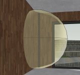
But you'd need very tiny speakers close together to re-create that wave front. Not a full range that transitions to more of a bending wave apparatus to be able to play high notes.
At least, that's what I get out of it. The gaps (and/or imperfections) are too big to be able to recreate the bubble you show. Too coarse pixels so to speak...
A big horn could probably get you closer, just find a way to get all frequencies in there (ala Danley?) without upsetting that wave front you've just created.
On the subject of Danley and big horns, I've always thought there's a lot of truth in this post by Tom:
Posted on one of the Western Electric threads: https://www.diyaudio.com/forums/multi-way/208799-western-electric-1928-100-a-63.html#post3025100
Even though I may walk on a slightly different path, Tom explains what is needed, right there. How phase does play a role in it. Which I believe as well. But also about the difficulties of our two ears compared to that mic. And don't forget the brain between those ears.
So even if you have the wave front just about right... is that enough to get the maximum illusion?
I know what you're trying to do, which is also part of the ideas behind the CBT. My post above isn't an example of a well done CBT though!
But you'd need very tiny speakers close together to re-create that wave front. Not a full range that transitions to more of a bending wave apparatus to be able to play high notes.
At least, that's what I get out of it. The gaps (and/or imperfections) are too big to be able to recreate the bubble you show. Too coarse pixels so to speak...
A big horn could probably get you closer, just find a way to get all frequencies in there (ala Danley?) without upsetting that wave front you've just created.
On the subject of Danley and big horns, I've always thought there's a lot of truth in this post by Tom:
It s just like Cheese cake and onions really!
Well to me anyway it looks like it, here is my take.
If one were to set out to describe the taste of cheesecake or onions to someone who had never tasted them, you probably would be able to find words that could give them “a mental picture” of what you’re talking about. In many of the posts here, it seems to me the discussion might be like this issue because until you actually taste these things, you are stuck with what you imagine the words mean and not knowledge of the taste /sensation the words refer to. Like they say, words are only the ladder we climb to grasp a new idea or understanding.
Thus when those who “have heard” try to describe to those who haven’t, the words they use do not convey the emotional experience of hearing it and that leave those who haven’t, wondering what the other have just smoked.
When bear talked about a single wide band source in post #496, point #1 And #2, unless you have heard what this sounds like, the words are just words.
I am not sure I can explain it any better than he can but it is something I have given a lot of thought to developing my own speakers encompassing one and two.
Start with the premise that a loudspeaker transducers job is to reproduce the input signal and nothing more, ideally it produces it with an amplitude proportional to that in the signal AND not producing any sound not part of the input signal AND to do all of that at the same instant in time as they components are present at the terminals.
Most of the “free sound” (not in the input signal) as well as some other problems increase in level faster than the level of the desired signal.
If you start with a loudspeaker that is satisfactory in a movie theater level, when you move that into a living room ALL of that undesirable stuff is greatly reduced as the operating level is greatly reduced compared to the intended use. The WE drivers are old by today’s standards but they were the state of art when made AND are a work of loudspeaker art, the product of a full out engineering and artisan effort and able to fill a theater.
By having one driver cover the range where your ears have the greatest acuity, they accomplished at least two things. With one driver covering that range, the time disparity is solved, the sound is radiated from one time. The acoustic phase one can think of as time as it represents how much the signal is delayed or advanced relative to the input signal. When you audition the phase shift crossovers produce though headphones, one concludes it is mostly not audible. When that effect is produced by two separate sources, there is more to the picture.
We hear in a way that makes this confusing or at least not so obvious. We hear from two points in space but the shape of our head, our ears all cause large changes which to a measurement person look like terrible flaws. We don’t hear the comb filtering, we don’t hear the changing frequency response or any of that stuff as flaws, were not even aware of it.
Instead, that is how we can hear what direction the sound is coming from, how high it is and so on. Our stereo hearing depends on these alterations to derive what to our consciousness is a live 3d stereo image there before us.
The purpose of a stereo is to “fake” this, in my mind it’s ultimate accomplishment is to reproduce another space realistically enough that you can forget it’s not real. My personal goal is eventually to capture and reproduce that live reality. if you’re interested in Stereo imaging, try the recordings at the bottom of the company download page.
These address a different part of the problem, picking up a live image, these being two channels are more or less your visual field of view, 3 additional channels extend the image around in a circle but obviously you can’t do that with head phones.
Anyway, the point is there are BIG ways our ears are different than a mic measurement.
A few examples of “how” the sound is radiated is audible and invisible on a one channel mic.
If you have ever stood in front of a large planar speaker like a full range electrostatic, full height ribbon or other homogeneously driven source, with a soft voice playing through one speaker, you hear a large source, it sounds big and sometimes, if you close your eyes, you really can’t hear how far away the source is, the voice may sound like it’s floating “somewhere” behind the speaker.
Now, how does it sound that way?
It’s because your ears hear a 3d picture even if a mic only senses one spot.
Take a typical small hifi speaker and do the same thing and while it might measure similarly, you will usually be able to also hear the source as the source. Your ears localize the origin because there are enough differences from the right to left that your learned ability allows you to identify where the sound is coming from in physical depth.
Take a Quad esl-63, or a manger bending wave transducer in a quiet place, play a voice through one and with your eyes closed, you will be surprised how little the apparent source is tied to the loudspeakers location, the voice can sound like it is well behind or even in front of the source.
How does it do that? These sources radiate as a simple point source and not a complex field which contains the clues that allow you to hear it’s depth, so now there is no “source identity” that your ears detect.
As the Unity and later Synergy horns got closer and closer to one driver in the output, I noticed this floating voice or source identity effect and was puzzled what it meant.
The WE driver on a proper horn would radiate as a simple source over much of it’s band too.
Who cares?
If you like stereo imaging, not the effects but things, people floating across the stage in front of you, this matters a lot. The mono phantom image is the heart of stereo, if you present two identical signals to your right and left ears, it sounds like its right in front of you (as it does with headphones except your lacking all that external directional head / ear stuff I mentioned earlier).
What harms this is any significant extra information that is not part of the ideal Mono.
If you have a speakers (as the majority of hifi speakers I have heard do) that shouts its physical location “here I am right here”, then while playing the mono signal you hear a mono phantom AND a right and left source.
To the degree they do that, they are greatly harming any ability to produce the original stereo image intensity, THEY should NOT be part of the image.
In commercial sound now, one rough measure of how well you can understand words is how much the direct sound is above the reflected sound level.
Large scale sound generally sucks because as the distance to the audience increases, so does the acoustic power required.
As the room’s volume increases, the surface area where the absorption is, increases at a slower rate than the room volume where the energy is stored. In a movie theater, the directivity the large horn size they used would greatly reduce the reflected energy, for the largest area of intelligibility, you want the sound to go where the people are and not the walls, ceiling or floor.
There is a thread about directivity, a powerful demonstration; set up your stereo outdoors in a normal configuration and listen to some of your favorite music with the best stereo images.
Do this and your feelings about the desirability of room effects will change. Re-creating that experience indoors in a living room requires significant directivity to avoid the room effects.
You set up a set of large Horn like those WE’s and sit in front and guess what, it sounds unreal enough to make most who have listened convinced they were on to something, and they were, even before stereo and that makes it pretty cool I think.
Think about how we hear and how / what we measure.
Lastly, I mentioned closing your eyes a couple times. Also that we have learned what all the artifacts our ears cause and take in are as positional and other spatial ques.
For the most part I don’t think people are aware how much “processing” our brains do for us without our knowledge.
Blind tests have a bad name because they strip away the inputs from other sense and prior knowledge leaving us to judge with only one sense like hearing.
While we see that effort when we take an eye sight or hearing test, there is no red light to indicate the tone and the you read random letters not words you can guess, you either hear or see or not.
Anyway, this is a cool example of how deep the” learned part” of our hearing is and how tightly it is tied to what we see, this is from a show on ones senses which was also amazing.
Try the Mcgurke effect;
Try The McGurk Effect! - Horizon: Is Seeing Believing? - BBC Two - YouTube
You only hear reality with your eyes closed
Best,
Tom Danley
Danley Sound Labs
I like big horns and I cannot lie,
those little horns make me cry.
Posted on one of the Western Electric threads: https://www.diyaudio.com/forums/multi-way/208799-western-electric-1928-100-a-63.html#post3025100
Even though I may walk on a slightly different path, Tom explains what is needed, right there. How phase does play a role in it. Which I believe as well. But also about the difficulties of our two ears compared to that mic. And don't forget the brain between those ears.
So even if you have the wave front just about right... is that enough to get the maximum illusion?
Last edited:
- Home
- Loudspeakers
- Full Range
- The making of: The Two Towers (a 25 driver Full Range line array)