@Anchan
To help you make a decision, read my posts #6389 and #6390 in the M2X thread. You can then calculate on your own at what power the amp transitions from Class A bias to Class B into the impedance load you desire (i.e. at currents of 1A or 0.75A).
Then, you can tell us, subjectively, and in your system how the lower bias sounds different than the higher bias.
Best,
Anand.

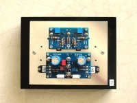
A F5 based frontend to pair with the M2OPS, instead of using an OPA551.
As discussed before at and around post #11.
https://www.diyaudio.com/community/...-and-maybe-a-power-whammy.390636/post-7134634
Patrick
As discussed before at and around post #11.
https://www.diyaudio.com/community/...-and-maybe-a-power-whammy.390636/post-7134634
Patrick
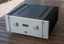
Beautiful work as always EUVL! Integrated amp with input selection and volume control (based on the chassis photo)?
Cheers,
Stephen
Cheers,
Stephen
I’m sure it will be worth the wait. I’ve been contemplating how to adapt the BA3 FE, so I’m interested to see what you have devised.
I built a channel and hooked up a light bulb tester. As expected it glowed brightly then dimmed as caps charged up but then after a few seconds it started to glow again, which I had read was not good (at least in the case of the F5). I noticed the DMM's on the 0R62 bias resistors showed 0.4V. Does this have something to do with the 4N26 (Q5)? Is something seriously wrong or can I proceed?
Something is obviously not right.
All optocouplers (including the 4N26 and the 4N35) have an LED which is ~1.2V forward bias.
Which corresponds to the voltage across the two resistors combined.
It is not different from the original M2 output stage.
Any changes are just fine tuning.
Patrick
All optocouplers (including the 4N26 and the 4N35) have an LED which is ~1.2V forward bias.
Which corresponds to the voltage across the two resistors combined.
It is not different from the original M2 output stage.
Any changes are just fine tuning.
Patrick
Are you certain? There is a couple hunred ohms of additional resistance in series with that LED. 0.4V across 0R62 indicates 645 mA, which is not huge.
Normally there should not be much current through those hundred-ohm resistors.
This is because the phototransistor on the optocoupler output side does not have much current to pass.
When it works properly, and there are many examples of such, the bias should be ~1.2A.
Across 2x 0R62 gives ~1.4V.
This equals to LED Vf + voltage drop across the 3x resistors in series with the LED.
If the output stage is under-biased (645mA), the light bulb should not light up, not ?
Patrick
Last edited:
I think it is normal for the DBT to glow bright, then dim once power supply caps are charged, then glow again, less brightly, as C3 charges up and current flows in the output stage. I don't think this necessarily indicates a problem.
This question comes up from time to time on the M2X thread and has been addressed there several times.
This question comes up from time to time on the M2X thread and has been addressed there several times.
- Home
- Amplifiers
- Pass Labs
- The M2 Output Stage in Class A/B, and maybe a Power WHAMMY?