Just curious, why did you choose the make a single sided board? Quite uncommon these days especially when the cost for double sided is so low.
It looks good thugh
It looks good thugh
peranders said:Just curious, why did you choose the make a single sided board? Quite uncommon these days especially when the cost for double sided is so low.
It looks good thugh
Because it's a simple design only requiring a few links. Why pay more for something that isn’t required?
Looking sharp Glen 
I have a problem with getting the 2N3055/MJ2955 set, Available only in quantity from Digikey, I don't need 800 of these.
Is the MJ15024/25 a good substitute? These I can get, and I'd like to have a few extra of these for other uses.
I have a problem with getting the 2N3055/MJ2955 set, Available only in quantity from Digikey, I don't need 800 of these.
Is the MJ15024/25 a good substitute? These I can get, and I'd like to have a few extra of these for other uses.
It looks betterG.Kleinschmidt said:Because it's a simple design only requiring a few links. Why pay more for something that isn’t required?
and the solder joints will be better with plated holes.peranders said:
It looks better
I feel like arguing today ....
 I'm with Glen. Allways try to do singleside PCB which everyone dedicated to this hobby can etch at home. F.e. Who needs the green soldermask and plated holes? Solderjoints will be good enough if the solder eyes isn't to small.
Because you have done it Per Anders, and also like the proffesionell looking isn't enough.
I really liked this project from the beginning because of the basic attitude but with a somewhat clever design.
Then I'm into tubes as well. This will be my first HiFi amp with tubes though. I only have experience in orchester amps with tubes before this.
🙂
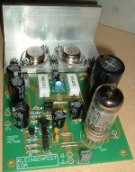
My implementation of this amp will be naked, with everything exposed, so I like the look of the board. It has a bit of a vintage look about it that suits this I think.
Vintage pcb?
MJL21193
We should have PCB's made of pertinax ! Oh, I love the pertinax smell of the PCB's ... but not Sony's old dark brown PCB's They have a somewhat sour smell 😱
I like the smell of the lightbrown PCB's. And when you unsolder an old pertinax PCB the fumes takes you to heaven 😀 Thats what real Vintage hardcore electronics is about.
Call me a geek, nerd or dork. I'll take it as a compliment
OK guys, you won't have any trouble with the soldering. I made all the pads nice and big (80 thou diameter minumum) and not being plated through, they will be much easier to rework after that incorrectly inserted polarized component lets out the white smoke.
MJ, those transistors will work fine. Way over-rated, but better hfe charachteristics and higher fT.
Cheers,
Glen
MJ, those transistors will work fine. Way over-rated, but better hfe charachteristics and higher fT.
Cheers,
Glen
Alrighty…. things are starting to go somewhere.
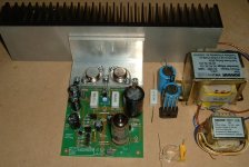
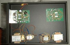
Shown below is a completely loaded board (minus the VAS transistor heatsink tab, which I have yet to cut) along with most of the externally mounted parts required for one complete channel.
To the right of the picture is the 60VA 24V transformer, the 30V 150mA transformer and the series resistor for the 12AX7 heater along with the bridge rectifier and filter capacitors.
I would recommend a minimum of 10,000uF be used here. The ones in the photo are a pair of 4700uF units that I’ve got at hand. I will go out tomorrow and but a few more, to have 3 of the in parallel for each channel.
Also shown in the photo are the 100n X2 class capacitor along with the coil former and the 6.8 ohm resistor for the hybrid load coupling / Zobel network. These components will be mounted on a bit of tag strip at the speaker binding posts.
For the PCB mount valve socket, I have elected to use a common chassis mount B9A unit with the chassis-mounting lug (preferably) removed.
This requires that short lengths of tinned copper wire be soldered to the lugs to protrude through the PCB holes. This is a bit of a fiddly procedure, but it allows any common 9-pin valve socket to be used.
I also prefer this to the available sockets designed for PCB mounting as it keeps the hot valve well clear of the PCB.
Cheers!
Glen
Attachments
Going into the chassis.
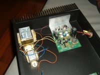
I have decided to mount both amplifier channels in one case and I am using a Hammond steel chassis intended / marketed for conventional Valve amplifiers. The chassis has heaps of room inside, so the transformers, power supply components and mains wiring can all be mounted well clear of the sensitive parts of the amplifier board. The stereo channels are kept well separated too.
The transformers will be mounted on stand-offs, a little bit above the base of the chassis to prevent the induction of eddy currents.
The heatsinks on either side measure 300mm X 75mm X 48mm and are rated at 0.37 degrees C / W.
I will make a varnished pine lid for the chassis with a sheet of aluminium screwed to the underside for shielding. A circular hole will be cut above each 12AX7 for clearance (the tip of each valve will protrube just a little) and ventilation.
Attachments
MJL21193 said:It has a bit of a vintage look about it that suits this I think.
Yes, even more so with the TO-3's mounted 😀
Re: Vintage pcb?
Pffwweeuee....no thanks!
Better, you could pick up a wrecked 50's - 60's Tektronics mainframe oscilloscope and salvage the ceramic component mounting strips. Then Silver solder all the comonents to those, for the ultimate reto look 🙂
Radioman62 said:MJL21193
We should have PCB's made of pertinax ! Oh, I love the pertinax smell of the PCB's ...
Pffwweeuee....no thanks!
Better, you could pick up a wrecked 50's - 60's Tektronics mainframe oscilloscope and salvage the ceramic component mounting strips. Then Silver solder all the comonents to those, for the ultimate reto look 🙂
G.Kleinschmidt said:ceramic component mounting strips.
Ceramic stuff is so cool, a shame there's not much use for it (anymore) in SS.
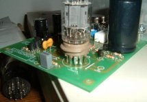
The tube socket floated above the board is a neat idea, i noticed there's even some spare space on the pcb between the socket and the lytics to drill a few holes.
Attachments
jacco vermeulen said:
Ceramic stuff is so cool, a shame there's not much use for it (anymore) in SS.
The tube socket floated above the board is a neat idea, i noticed there's even some spare space on the pcb between the socket and the lytics to drill a few holes.
Hmmm...... if you mean to add extra support to the valve socket, it really isn't required. It's quite rigid with 9 leads of 0.8mm tinned copper wire.
MikeW said:Glenn, Please send me an e-mail so I can send you the $ Thanks, Mike.
OK Mike, YGM
I've just made an update to the K10A website too, including a circuit description:
http://users.picknowl.com.au/~glenk/K10A.HTM
Cheers,
Glen
Interesting design.
I noticed that Q13 in the schematic is labeled BD139.
That's an NPN transistor. It is shown as a PNP transistor.
Perhaps you meant to label it a BD140?
ZAP
I noticed that Q13 in the schematic is labeled BD139.
That's an NPN transistor. It is shown as a PNP transistor.
Perhaps you meant to label it a BD140?
ZAP
G.Kleinschmidt said:
Yes, even more so with the TO-3's mounted 😀
Hi glen,
I like the look of the TO-3 package - explosion proof. Your progress looks good, though you haven't peeled and polished your caps...
MikeW said:Glenn, Please send me an e-mail so I can send you the $ Thanks, Mike.
Glen, are you taking payments yet?
- Status
- Not open for further replies.
- Home
- Amplifiers
- Solid State
- The Kleinschmidt 10A