Between the motor, armboard, and mounting hole you can have a good +/- 4mm of tolerance. Best to measure P2S distance when mounting the arm.
debugging inop unit
WRT my inop SP-10mk2. The fault tracing page in the service manual fits the problem description perfectly. (A) Switching on does not cause turntable to rotate. Incidentally, The lights come on, the switch lights switch when pressed. the neon bulb comes on. The table turns freely with finger push. (Brake not on)
First block says check connector board for voltages. They are perfect. [I have 2 SH-10E's and the both check perfectly and both run my other table perfectly.]
I do not know best way to see if the brake operates or not (second step). Table is upside down with PCBs exposed. Platter off and power on.
Or, if someone the probable answer, I can just go there.
Thanks,
Don
Brake is operated by a solenoid under the black trip piece under the platter, it makes a distinct click when engage/disengage. If it's clicking, it's working.
Thanks, Jim.
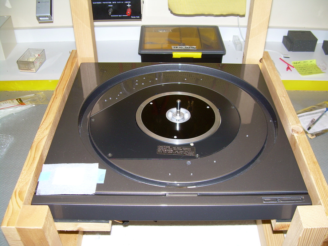
Flipped the unit over(PSU off), took the plate off, and turned the PSU on. Brake on. Turned the PSU off, brake off. It works and I learned something.
To anyone, back on the fault trace.
First, they say 0V is at chassis ground. There is a 0V lead in the boards and I am using that as ground. Correct?
Next was to check the Voltage at e15. 29.78V which I called OK on a 32.5V circuit.
Next was to check voltage at P3. Asking for 0.7V. Stopped here. One is the notes on the circuit diagram says that all voltages in a square rectangle should be at 33.3 rpm. Parenthesis are stopped. P3 is in a rectangle. You are not supposed t press start with no turntable but mine doesn't spin and platter off to work on it upside down so I'm thinking I can just forge ahead. I am doing this with the boards facing me. OK?
Also, being a newbie, I really don't understand the three pins on P3 and I am not good enough to back trace them on the wiring board view so what am I measuring at each pin. Better yet what is it used for (P3)?
Thanks for the help.
Don
You can take squares of cardboard glued together to create four blocks for each corner of the chassis. Fashion these a tad taller than the spindle and attach with tape. You can then flip the 'table over with the platter on and compress the blocks a bit as needed to ensure the the spindle shaft has contact with the thrust bearing and is not hanging in the air. Works a treat, and far easier to do diagnostics.

Attachments
@donhughes111
You can also build yourself a support like this, you can do the calibrations without constantly overturning the turntable.... It is not complicated to build it
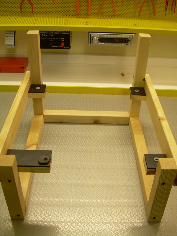
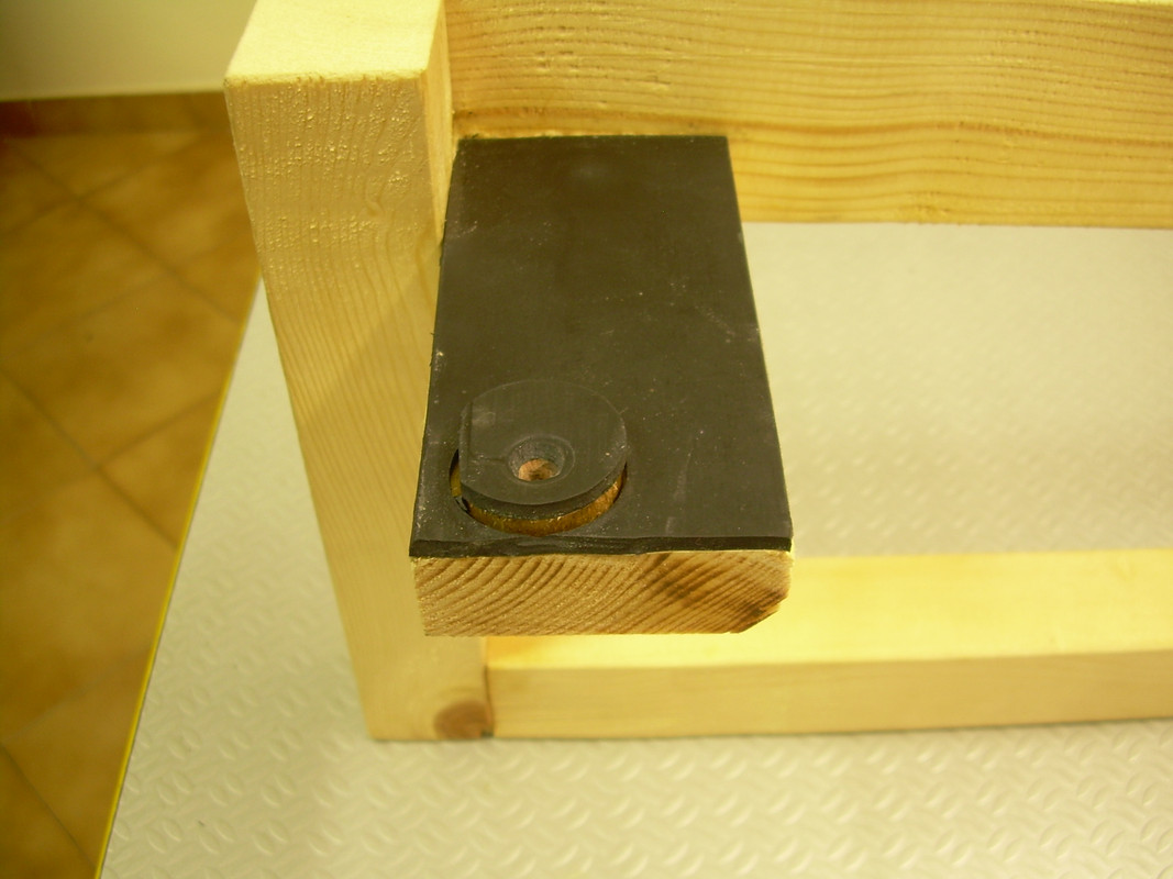
You can also build yourself a support like this, you can do the calibrations without constantly overturning the turntable.... It is not complicated to build it
Last edited:
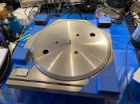
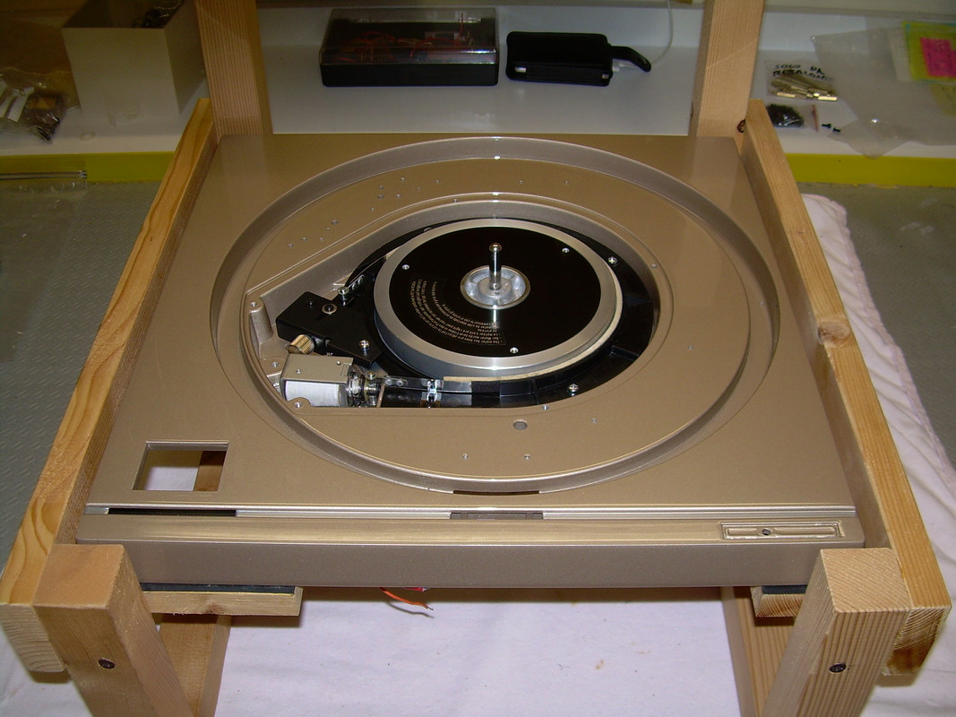
I am about to embark on a build to hopefully construct the best possible SP10mk2 I can. Removing the motor from the SP10 chassis and installing it in its own plinth with new Delrin platter and servo Linear Tracker.
As I am waiting for parts I got to thinking, a dangerous pastime I know.
The mk2 bearing is quite small at about 7mm. So I measured platter deflection and bearing clearance in the middle of the platter. Bearing slop was about 0.1mm and deflection with very light pressure was about 0.5mm.
Measuring the OEM housing it could be reamed to 10mm leaving 1mm of the OEM bush. However I think this would reduce bearing rigidity which is obviously not a good thing.
The next thought was to machining a new bearing housing to take a larger diameter spindle that would be a drop in replacement in the SP10 motor housing. This would require machining a new bottom motor housing. The housings can be made slightly larger to increase rigidity.
If the FG ring ID can be machined larger I could fit a 14mm spindle, otherwise a 10 or 12mm spindle can be used.
Obviously I do not want to machine the FG in my good motor.
If anyone has a dead mk2 motor that they would be prepared to part with please let me know.
Last edited:
These measurements were on a bearing that is almost pristine, virtually no wear. There are upgrades for the SL1200 bearing the Timestep SL1200 bearing is 11.1mm OD.
Technics upgraded the bearing in the mk3 to 16mm so a larger spindle in the mk2 combined with a SS/Delrin platter should be a significant upgrade.
If I can get the subplatter apart I will either make a new SS subplatter or fix the magnet assembly to bottom of the SS platter.
Pontificating ATM until I find another motor to dismantle.
@warrjon
I prefer not to indulge myself with the changes, I just want to listen to the vinyls I own and continue to buy, not to spend the years I have left to live experimenting.
I prefer not to indulge myself with the changes, I just want to listen to the vinyls I own and continue to buy, not to spend the years I have left to live experimenting.
How did you measure the bearing clearance? I ask because 1/10 of a mm isn't a remotely precise measurement for such things.
On a granite surface plate with a test indicator and calibrated weights. Before I retired I was a repair tech in a calibration laboratory so I have a pretty good setup for measurement.
Power supply hum breakthrough in W&F measurements.
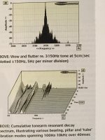
Hi Fi News has tested the mkII (Vol 55, No. 11, November 2010) and reported mains related breakthrough, principally 50 Hz, 100 Hz and 150 Hz on UK 50 Hz mains. This can be seen polluting the W&F measurements. The 100 Hz breakthrough is the worst and can be seen clearly in the ±100 Hz sidebands, which rise ~15 dB above the noise floor. Comparing this with the SP10R results (Vol 63, No. 06, June 2018), which has a 7 dB improved Hum & Noise, the principal measured difference between the 10R and the mkII, is seen in the flutter results. Is this due to the mains induced hum? Without these sidebands the 10mkII still measures state-of-the-art on W&F. The transformer induced hum in moving coil's does required sufficient distancing of the power supply from the cartridge. The 10R uses a switched mode power supply. Would a SMPS improve the performance of a mkII? I realise SMPS are noisy compared to LPS, but will this mainly hf noise be less deleterious to performance than the mains related hum of a LPS?
Hi Fi News has tested the mkII (Vol 55, No. 11, November 2010) and reported mains related breakthrough, principally 50 Hz, 100 Hz and 150 Hz on UK 50 Hz mains. This can be seen polluting the W&F measurements. The 100 Hz breakthrough is the worst and can be seen clearly in the ±100 Hz sidebands, which rise ~15 dB above the noise floor. Comparing this with the SP10R results (Vol 63, No. 06, June 2018), which has a 7 dB improved Hum & Noise, the principal measured difference between the 10R and the mkII, is seen in the flutter results. Is this due to the mains induced hum? Without these sidebands the 10mkII still measures state-of-the-art on W&F. The transformer induced hum in moving coil's does required sufficient distancing of the power supply from the cartridge. The 10R uses a switched mode power supply. Would a SMPS improve the performance of a mkII? I realise SMPS are noisy compared to LPS, but will this mainly hf noise be less deleterious to performance than the mains related hum of a LPS?
Attachments

Hi, new to the site and I wonder if anyone can help? Based in Berkshire UK and looking to get my SP10 serviced and a plinth built for it, is their anyone out there that could help?
Phonomac is the person to contact, he's on various Forums such as Art of Sound, Pinkfish MediaHi, new to the site and I wonder if anyone can help? Based in Berkshire UK and looking to get my SP10 serviced and a plinth built for it, is their anyone out there that could help?
- Home
- Source & Line
- Analogue Source
- The Incredible Technics SP-10 Thread