gaborbela said:Did you ever com paired your amplifier with another DIY amplifier or some better quality from the store?
What size of transformer use for the power amp section .
300VA is enough?
It's a difficult question. Anyway most of commercial based amplifiers have
own sonics, some are bright sonic and some are cool sonic. I have
various kinds of tube amps and semiconductor amps even Class-D amps.
Within these amps, my hybrid amp occupies at the "NEUTRAL POSITION"
without coloring, not too much bright, not too much cool, not hussy. but
having tube tasting sonic. I positioned this hybrid amp as the "METRIC
STANDARD" to benchmark other amps' sonic.
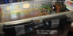
Regarding to the transformer, it is used for only heater of the tubes
and small current into two tiny tubes (DC270V, 10mA x 2ch). So 30VA
rated transformer is enough. (See attached photo).
Regarding to your PCB design, I found Pin #4 and #5 are not connected
to the AC6.3V winding of the transformer. It is for the tube heaters.
Attachments
Hello
I forget the heater because it was not on the schematic .
But is no to late .I will fix it .
I ask the transformer size for the mosfet part if 300VA enough .
Thanks
I will correct the lay out and I posted again .
Greetings
I forget the heater because it was not on the schematic .
But is no to late .I will fix it .
I ask the transformer size for the mosfet part if 300VA enough .
Thanks
I will correct the lay out and I posted again .
Greetings
Why, and what's the reason?
If you like cathode-followers better its your choice.
By "Schade"-connecting the MOSFET, you can dial in the right amount of local feedback to fit your preference.
gaborbela said:I ask the transformer size for the mosfet part if 300VA enough .
200VA rated transformer is enough as shown in the attachment.
The secondary winding should be 28V to 30V (w/ CT) and 6A rated
is better to assume enough current margin. You can merge the windings
into one transformer for the tube portion of AC115V 50mA and
AC6.3V 1A so that you can use only one transformer.
Attachments
Hello
Thank you .
That transformer for both side or one side ?
I fixed the lay out , I forget .You know I look at the schematic and thinking about the best solution for the layout .
Believe me is not easy to do it with out any software .
I did made already 5-6 layout with out any program , some of them more complex .
HERE I POST THE GOOD LAYOUT !
Not tested yet but it supposed to be good . Please check it carefully .
These was design for vertical mosfet Toshiba 2SK1529 .
Greetings
Attachments
Hello
OK I saw the picture you posted about the transformers now I understand .
Thank you
If I can offer a great amplifier , simple great sond (of course with good quality parts .
The ProFet.
I use Exicon laterals , Caddock resistors , Rusian 0.22uF PIO capacitors on the PC board , 8x10 000uF Nippon Chemi-com KME type capacitors for the pover supply , pure silver wire with cotton tubing , WBT solder , 500VA toroid etc . Class A al the way .
The sound incredible good .
I have the PC board layout if you needed.
Two lateral mosfet and 2Jet active parts 8 resistor 3capacitor on the PCboard .Unfortunately not SE , but still great amp.
Greeting
gaborbela said:
That transformer for both side or one side ?
A 200VA transformer can feed to L/R channels of MOS FET power
sections.
Hello
I have 285VA transformer, that will be great , I only need to wind on some wire for the tubes and the heaters . There is a another sec on it 0-60V low VA rating max40- 50VA I will make that for the tube part .
Regards
I have 285VA transformer, that will be great , I only need to wind on some wire for the tubes and the heaters . There is a another sec on it 0-60V low VA rating max40- 50VA I will make that for the tube part .
Regards
ja2dhc said:How do you do, Sajti, from Japan. The circuit schematic of my hybrid
amplifier is based on your amp whose schematic is seen below.
You used IRF-540 as the MOS FET.
Regarding to MOS FET, I used a small packaged one (I2PAK package)
at first then it became easily burn out due to heat problem. I changed
to TO-3P packaged one (FS22SM-12A) then it did not become heat
problem. I believe whatever kind of MOS FET in TO-3P package with
following electrical spec can work in my schematic.
D-S withstanding voltage : 100V or bigger
Max Current: 10A or bigger
Max Input capacitance: 8000PF or less
One of my fried in Japan successfully made a similar amp with different
MOS FET with TO-3P package and forced air cooling heatsink as shown
below. His amp does not have heat problem, either.
http://ja1cty.servehttp.com/mosfet/nakai-amp.jpg
Hi,
I found, that low current mosfets (low capacitances) are better for this application. I don't work with this amplifier long time ago.
The best sound I found, was with IRF510 or 520, but they need huge heatsinks, and lot of force air cooling.
For tubes: The best, I found is parallel connected 5687, or ECC99, with at least 10mA for each triode.
The thermal runaway problem was with the current generator. Finally I used feedbacked type single transistor, and avoid the source resistor from the source follower.
Sajti
Hey ja2dhc,
This is how I will build my Schaded hybrid:
Delivery of the drain-chokes are delayed until end of this month. Have everything else and bought 2 pcs Arctic-Cooling Alpine Pro 7 today. Also bought 2 SMPS 24V/5A from China at eBay.
This is how I will build my Schaded hybrid:
An externally hosted image should be here but it was not working when we last tested it.
Delivery of the drain-chokes are delayed until end of this month. Have everything else and bought 2 pcs Arctic-Cooling Alpine Pro 7 today. Also bought 2 SMPS 24V/5A from China at eBay.
I have lot of IRFP250N, and I will give them a chance! Low Cgs (80pF), so parallel ECC99 with 6.8kohm anode resistor can drive them easily.
But now I have to finish the current hybrid project (250W/8ohms, balanced)
Sajti
But now I have to finish the current hybrid project (250W/8ohms, balanced)
Sajti
One another version:
I made balanced version of this amplifier. It's very good, because I found, that the MOSFETs have better sound, if the bias is higher. And the balanced version used single 20V power supply, and had no DC servo. (of course MOSFET matching is necessary)
Sajti
I made balanced version of this amplifier. It's very good, because I found, that the MOSFETs have better sound, if the bias is higher. And the balanced version used single 20V power supply, and had no DC servo. (of course MOSFET matching is necessary)
Sajti
sajti said:I found, that low current mosfets (low capacitances) are better for this application.
Hi ! sajti,
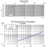
The input capacitance of my MOS FET is 4,600PF given by the datasheet.
The actual frequency response is shown in the attached photo. I believe
this result is enough to get good sonic. Regarding to heatsink, yes,
forced air heatsink is mandatory required otherwise 50cm x 50cm
x 10cm sized natural cooling heatsink is needed. I used PC CPU purpose
heatsinks as shown in the below URL.
http://ja1cty.serevehttp.com/mosfet/FET-outside.jpg
For tubes: The best, I found is parallel connected 5687, or ECC99, with at least 10mA for each triode.
The thermal runaway problem was with the current generator. Finally I used feedbacked type single transistor, and avoid the source resistor from the source follower.
Sajti [/B]
In my case, 10mA into a 6688 triode connection. Due to low rp and Rl of
the tube, enough frequency response is obtained as well as sonic.
To avoid thermal runaway, I increased the source resistor of the CCS
FET to 1ohm instead of your design of 0.68ohm and I used TO-3P
packaged MOS FET. These countermeasures with forced air, thermal
runaway has been disappeared. My friend made 3 units of similar amps
without thermal runaway.
Attachments
Thanks to share Your results!
If You use the MOSFET as source follower, the most important capacitance is the Cgd. That must be as low as possible.
The biggest problem is not the frequency response, but this capacitance is nonlinear, and can results distortion.
Now I checked some new Fairchild mosfets. The most interesting can handle Uds=900V Id=9A, and Pd=280W, and Cgd=14pF!!!
Sajti
Input capacitance of a source follower is bootstrapped, so an effective input capacitance is much smaller than when measured with source grounded. Also, MOSFETs with higher input capacitances usually have higher forward transconductance, that means lower variations of Vgs needed for the same output current variations.
Wavebourn said:Input capacitance of a source follower is bootstrapped, so an effective input capacitance is much smaller than when measured with source grounded. Also, MOSFETs with higher input capacitances usually have higher forward transconductance, that means lower variations of Vgs needed for the same output current variations.
I agree with You. The most problematic is the Cgd, which has large voltage swing, same as the output voltage.
Sajti
sajti said:
I agree with You. The most problematic is the Cgd, which has large voltage swing, same as the output voltage.
Sajti
One more follower on top helps bootstrapping it.
Yes, but I dont want to make it as much complicated. But it's possible, so I will check it!
Sajti
Sajti
Hello
I think I will try a couple power mosfet I have at hand .
IRFP150N
IRFP044N
IRFP240
And Toshiba 2SK1529 , I have some orig. Hitachi 2SK1058 but only 7A ,100W 160V.
May be I try that to .
I will se which one feet the best these amp.
Greets
I think I will try a couple power mosfet I have at hand .
IRFP150N
IRFP044N
IRFP240
And Toshiba 2SK1529 , I have some orig. Hitachi 2SK1058 but only 7A ,100W 160V.
May be I try that to .
I will se which one feet the best these amp.
Greets
sajti said:Yes, but I dont want to make it as much complicated. But it's possible, so I will check it!
However, it will consume some extra power, though...
- Status
- Not open for further replies.
- Home
- Amplifiers
- Tubes / Valves
- The Hybrid Class A amplifier