
See post #477
"If you received "bonus" FETs, they are marked with an "X" on the backside. The four FETs without an "X" on the backside are the ones to use. Either NFET can be paired with either PFET.
The P1 and P2 adjustment pots should take care of differences between the FETs pairings that I have distributed.
You should not need to use sockets for the FETs unless you plan to experiment with different FETs."
Some of the HGB builders have expressed interest measuring and/or matching FETs for the output stage. The matching procedure I used for the FETs distributed with the HGF PCBs that based on keeping the ratio of gm(NFET)/gm(PFET) in a range between about 1.05 and 1.15. For some FET choices (part numbers) the PFET have higher gm than the NFETs and the ratio might be in a range .87 to 1.0.
I have developed a simple, in-circuit procedure that appears to work well and only requires a sine-wave generator, one or more multimeters capable of making reasonably accurate measurements in the 15 mVrms to 100 mVrms range, and a 5W or higher output load resistor of 4R, 6R, or 8R depending your speaker impedance.
The procedure uses the HGF PCB itself to make in-circuit measurements. What is measured is the Vrms voltages across the drain current sense resistors R1 and R2, as well as the Vrms voltage between the input and output of the output stage.
What is calculated from the measurements is the effective transconductance of each FET at the operating point with the applied load resistance Rload. This transconductance value includes the effects due to lambda, the channel-length modulation factor, or equivalently, Rd the FET drain resistance (counterpart to the triode plate resistance Rp).
The calculations are trivial:
gmNFET = (Vrms(R1)/R1)/Vrms(Vin-Vout)
gmPFET = (Vrms(R2)/R2)/Vrms(Vin-Vout)
The output impedance Rint can be calculated as:
Rint = Rload*Vrms(Vin-Vout)/Vrms(Vout)
The damping factor is:
DF=feedback_factor*8/Rint
Procedure:
- Install FETs to be measured. (You will wish you had terminal blocks for the FETs and a riser bar on the heatsink as described in the Users Guide.)
- Attach Rload.
- Adjust bias current and output offset. (It is best if the heatsink temperature is stabilized.)
- Apply a sine wave input to obtain roughly 2.83Vrms output.
- Measure Vrms(R1), Vrms(R2), Vrms(Vin-Vout). (Vin is measured at test-point FEOut).
- Perform the above calculations.
Well, I have ordered a batch of PCBs and waiting to receive them.
Meanwhile, I began gathering components. I have 2 questions:
1. Trimmer potentiometers P1 and P2 should be multi-turn or single-turn? In the pictures of the original build I noticed that they are single-turn, while in some other build the builder used multi-turn.
2. Regarding optocouplers, the BOM says PC817 (single), while the Mouser and digikey Ref Nos. refer to double versions LTV-827 and LTV-825, respectively. Does it make any difference? Can I use 2 PC817?
Thank you!
You can use multi-turn if you like. The single-turn trimmers work well, but require small rotational adjustments to make fine adjustments.Well, I have ordered a batch of PCBs and waiting to receive them.
Meanwhile, I began gathering components. I have 2 questions:
1. Trimmer potentiometers P1 and P2 should be multi-turn or single-turn? In the pictures of the original build I noticed that they are single-turn, while in some other build the builder used multi-turn.
2. Regarding optocouplers, the BOM says PC817 (single), while the Mouser and digikey Ref Nos. refer to double versions LTV-827 and LTV-825, respectively. Does it make any difference? Can I use 2 PC817?
Thank you!
You can use a pair of single optos (PC817). The primary concern is that the current transfer ratio isn't more than around 300%.
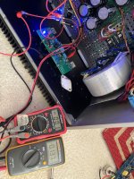
It’s a dual mono Antec 18vac trafo paired with Lt4230 rectifiers followed by 100kuf capacitance each psu board. I get around 28vdc unloaded as my home voltage is slightly higher most of the times. Cabinet is from my SissySIT reusing 5U/400mm sufficient heat sinks for higher bias.
Both the channels powered problem free and after an hour bias is very stable at 0.137vdc and offset around 0.05mV
Both the channels powered problem free and after an hour bias is very stable at 0.137vdc and offset around 0.05mV
Why should CTR be less than 300%?You can use a pair of single optos (PC817). The primary concern is that the current transfer ratio isn't more than around 300%.
I do not know if 300% is an exact limit, but at some point the bias circuit adjustment will be not be possible without changing some resistors.Why should CTR be less than 300%?
Thanks. I appreciate that the circuit is sensitive to CTR amongst other things. Just wondered whether there was some fundamental reason why 300% was the upper limit. As a practical matter, most optocouplers seem to have a CTR of less than 100% at input currents of a few millamps with the exception of photo darlingtons.
Recently I did some new THD measurements using pairs of 2SK3497/2SJ618.
The HGF was running with OPA551 at Vdd = +/-23.5 V, 1.25 A bias and no global feedback. The test frequency was 1 kHz.
The damping factor DF = 128 and is twice as high as that of Fairchild MOSFETs.
The HGF was running with OPA551 at Vdd = +/-23.5 V, 1.25 A bias and no global feedback. The test frequency was 1 kHz.
The damping factor DF = 128 and is twice as high as that of Fairchild MOSFETs.
Attachments
THD is not the whole picture.
You need to compare H3 to the standard OPS.
The above Toshiba pair works better with source resistors.
See also here for comparison between standard M2OPS, and that without R source (only OPS, no frontend).
https://www.diyaudio.com/community/...tage-perfectly-integrated.406024/post-7686147
If you want to have better results, consider trying Yfs matched 2SK1530/2SJ201.
Patrick
Patrick, I don't claim that THD is the whole story.
H3 is in any case at a very low level, H2 is dominant and I'm very satisfied with the results.
Does it sound better than with Fairchilds?
A good question. I don't know it but believe that:
Sometimes a myth is stronger than the truth, and truth can sometimes lie
To see it all for what it was you need an uncorrupted ear and eye
Was the journey worth it, only time will tell
Still looking for Nirvana, in my DIY's Spell...
Last edited:
I recently purchased 20 x OnSemi FQA28N15 and 10 x IXYS IXTQ36P15P FETs from Mouser.
I have tested all of the IXTQ36P15P FETs in one channel of the HGF paired against the same FQA28N15. The results were excellent with 1W/8R and 2W/4R in the range 0.0013% - 0.004%. I measurements AC drain currents with 4R and 8R loads and using some new software computed the load-line gms and estimated the "actual" gms, where Vds is constant. The gms had a standard deviation of about 2%.
I have tested all of the IXTQ36P15P FETs in one channel of the HGF paired against the same FQA28N15. The results were excellent with 1W/8R and 2W/4R in the range 0.0013% - 0.004%. I measurements AC drain currents with 4R and 8R loads and using some new software computed the load-line gms and estimated the "actual" gms, where Vds is constant. The gms had a standard deviation of about 2%.
Similarly I tested a subset of the FQA28N15 FETs paired with the same IXTQ36P15P FET. I found that the THD were all very low and the gms had a standard deviation of about 1%.
Bottom line: The OnSemi FQA28N15 and IXYS IXTQ36P15P FETs from Mouser function exceptionally well in the HGF, and extensive matching doesn't appear to be required.
I have tested all of the IXTQ36P15P FETs in one channel of the HGF paired against the same FQA28N15. The results were excellent with 1W/8R and 2W/4R in the range 0.0013% - 0.004%. I measurements AC drain currents with 4R and 8R loads and using some new software computed the load-line gms and estimated the "actual" gms, where Vds is constant. The gms had a standard deviation of about 2%.
I have tested all of the IXTQ36P15P FETs in one channel of the HGF paired against the same FQA28N15. The results were excellent with 1W/8R and 2W/4R in the range 0.0013% - 0.004%. I measurements AC drain currents with 4R and 8R loads and using some new software computed the load-line gms and estimated the "actual" gms, where Vds is constant. The gms had a standard deviation of about 2%.
Similarly I tested a subset of the FQA28N15 FETs paired with the same IXTQ36P15P FET. I found that the THD were all very low and the gms had a standard deviation of about 1%.
Bottom line: The OnSemi FQA28N15 and IXYS IXTQ36P15P FETs from Mouser function exceptionally well in the HGF, and extensive matching doesn't appear to be required.
Thanks Lynn, this is great news! I struggled to find FQA36P15P parts and knowing the available IQXT parts work well is fantastic news for builder wanting to mimick the original design.
Last edited:
Here are some spectral sweeps of "randomly" selected OnSemi FQA28N15 and IXYS IXTQ36P15P FETs referred to in post #777. The bias current is 1.3A with 28.8V rails, and 12dB global negative feedback.
These FETs in the HGF really like to drive into 4Ohm loads.

These FETs in the HGF really like to drive into 4Ohm loads.
- Home
- Amplifiers
- Pass Labs
- The Holy Grail Follower Output Stage