

I made the second board it looked good but I messed up the filter on the negative rail. I tried to fix it but had to bypass it in the end. The 3030i speakers needed a burn in and sound so much better now (I really thought I had a duff pair). Also, I have wired up the Celestion Ditton 25 speakers and I am impressed. The HGF is a very good amp, it is very revealing while still forgiving with poor recordings.I needed to listen to a different copy of Hotel California because a bit at the beginning sounded weird to me but the Qobuz version was the same. I took it to full volume listening to Sir Duke Stevie Wonder and it did not clip or distort. I am using a SE input and will get around to using my balanced dac soon. It is currently running at +-28.5V and the bias is at 185mv, the heatsinks are just warm at the base. I can’t turn the fans down any lower or they will not start. I have some Noctua 12v 900rpm 140mm fans coming today that I hope will run a bit slower and I hope will look ok. The power supply is cool on the top but warm on the sides where the 2 LRS-200-24 smps are bolted so I will not bias them any higher at the moment. If I did this again I would put the filters on a separate board inside the psu case and spread the smt bits out a tiny bit more. I like the power connectors, the plugs were fiddly but worth it and I can put sockets on my other amps if I want.

You might consider using a PCM fan controller such as TC642B: https://www.microchip.com/en-us/product/TC642BI can’t turn the fans down any lower or they will not start.
It will work with ordinary 2-wire (non-sensing) Noctua fans.
I cancelled the Noctua fans as they were going to take too long to arrive and got a pair of Artic P140 fans. These are smaller and the amps look less top heavy now. They run/start at lower speeds. The heatsinks are warm and the fans are silent. The WIIM Ultra wasn’t silent and I could hear a slight hum with my ear next to the tweeters. Not 100% sure it is the WIIIM or my layouts ground as it was connected SE, when my headphones are connected to the WIIM it is silent.
I have now put in balanced DAC using a coax output from the WIIM. The system is totally silent now.
A second cheap 10A switch has failed on my trigger bypass circuit but as I have finished testing everything for a while I will remove it.

I have now put in balanced DAC using a coax output from the WIIM. The system is totally silent now.
A second cheap 10A switch has failed on my trigger bypass circuit but as I have finished testing everything for a while I will remove it.
Several inconsistencies have been found between the schematic (fig. 2) and the PCB layout (fig. 4) of the Build Guide (post #303).

- The labels for resistors R11 and R12 are reversed in the schematic.
- The positions of D1 and R7 are reversed.
- The positions of D2 and R8 are reversed.
- The positions of P2 and R9 are reversed
for what it's worth, Mouser is showing that nearly 5K of the part FQA36P15 is "On Order".
Strangely, Mouser now only shows 2 pieces on order!!!

Someone swooped in a couple weeks ago and bought almost all of them. I was bummed out I didn't grab any, but it was an 84 week backorder so I figured there was no rush.
I do have the IXTQ36P15P that Lynn has said appears to be just as good. He also mentioned matching may not be required, which was my hold up as I'm still pretty new to all this stuff.
I do have the IXTQ36P15P that Lynn has said appears to be just as good. He also mentioned matching may not be required, which was my hold up as I'm still pretty new to all this stuff.
I have made some careful measurements of a sampling of FQA36P15 and the IXYS IXTQ36P15P FETs. Other than expected variations of parameters, I detect no significant differences. The part name of the IXYS FET also suggests that it is the same underlying FET design.
The FQA36P15 samples contained both some "old stock" Fairchild FETs from 2012-2015 and more recent purchases from Polida on EBay. Again, the parameter variations are what can be expected within and between batches of FETs. There had been considerable concern that the EBay FETs were fakes. The only "strangeness about them is that their leads appear to be spot welded near the package. Were these FETs removed from PCBs by cutting the leads and reattaching new leads or is there some other explanation?
Bottom line:
Below is an image of my FET measurement setup. It is designed for accurate and repeatable measurement of gm and lambda at a given operating point. Mounted to the heatsink are two PCBs, one for PFETs and one for NFETs, using the same PCB artwork. The test signals and measurements are made using USB and LAN interfaces to the instruments under control by a GNU OCTAVE (MATLAB) program.

The FQA36P15 samples contained both some "old stock" Fairchild FETs from 2012-2015 and more recent purchases from Polida on EBay. Again, the parameter variations are what can be expected within and between batches of FETs. There had been considerable concern that the EBay FETs were fakes. The only "strangeness about them is that their leads appear to be spot welded near the package. Were these FETs removed from PCBs by cutting the leads and reattaching new leads or is there some other explanation?
Bottom line:
- If you cannot find new FQA36P15 FETs, the IXYS IXTQ36P15P FETs are available.
- If you have the EBay EBay FETs and they sound good in the HGF, continue to use them.
Below is an image of my FET measurement setup. It is designed for accurate and repeatable measurement of gm and lambda at a given operating point. Mounted to the heatsink are two PCBs, one for PFETs and one for NFETs, using the same PCB artwork. The test signals and measurements are made using USB and LAN interfaces to the instruments under control by a GNU OCTAVE (MATLAB) program.
More good news:
I have found another excellent FET pairing for the HGF: Vishay IRFP240 + Harris IRFP9140.
Too bad that the Harris FETs are nearly impossible to find.
HGF configuration: +/-29V rail voltages 1.25A bias 12dB negative feedback
Measurements:
Damping factor: 160
Distortion: see plots
25 Watt 1kHz 8R load spectrum

1kHz Watt and Frequency Sweeps:

I have found another excellent FET pairing for the HGF: Vishay IRFP240 + Harris IRFP9140.
Too bad that the Harris FETs are nearly impossible to find.
HGF configuration: +/-29V rail voltages 1.25A bias 12dB negative feedback
Measurements:
Damping factor: 160
Distortion: see plots
25 Watt 1kHz 8R load spectrum
1kHz Watt and Frequency Sweeps:
Hi Lynn - Wonderful news. Did you happen to try any of the Vishay / IR / Infineon 9140s? Is there a reason for noting the Harris part, or is it just the only one you had on hand / tried?
I only ask b/c Nelson demonstrated that non-Harris 9140s didn't have the same 'issue' similar to the commonly discussed non-Harris 9240s.
Not questioning your results at all, I'm just wondering if other 9140s may be just fine also and/or are simply as yet untested / unknown in your circuit.
Thanks!
I only ask b/c Nelson demonstrated that non-Harris 9140s didn't have the same 'issue' similar to the commonly discussed non-Harris 9240s.
Not questioning your results at all, I'm just wondering if other 9140s may be just fine also and/or are simply as yet untested / unknown in your circuit.
Thanks!
The supplied parts are fine. We are using IRF140 and 9140 which do not have the issues found in the IR version of the IRF9240, which is a shift in transconductance value at midrange frequencies.
On another topic,
I have had communication with people who are still not reassured as to the Harris vs Vishay P channel
Mosfets for this project, so I present the attached graphic to further quell attacks of Audio Nervosa...
You see here a gain test of five P channel power Mosfets, biased at 0.5 amps and 10 volts driving
8 ohms Common Source. At the top we see the Harris 9240, then below that are the Harris and
IR versions of 9140. Slightly below that is the Fairchild 12P20 and at the bottom, shelving down
about 3 dB going into the midrange, the IRFP9240.
Interesting, the devices with...
Neither the Harris nor the Vishay 9140s exhibited any shelving behavior in my tests.
But, the Harris IRFP9140 FETs have an unusually low lambda parameter 1.85e-3, which is rarely seen in a PFET.
The Vishay version has a lambda of 11.7e-3.
What difference does it make? There is a simple relationship between the lambda of a MOSFET and the plate resistance of a triode. Larger lambda values cause an increase in gm as rail voltage increases. However, gm decreases as the load resistance increases, gm more sensitive to speaker load impedance. The net result is that the 2nd harmonic varies more with speaker impedance.
If you cannot obtain the Harris 9140, you might try the Vishay version. You might like the sound. I am not sure what might be the best NFET to pair it with.
Here is a table that summarizes my recent FET measurements.
The operating point of the measurements was Vds0 = 24V, I0 = 1.3A.
^ Thank you so much for taking the time to explain the process and the influence of the Lambda. Easy to tell that I am still learning re: what characteristics of devices "matter" in various circuits, particularly when they carry the same part numbers. Fascinating.
The good news is that I have a variety of 9140s (including the Harris). My personal HGs will likely stay as-is with the Fairchild parts, but I am always curious how things behave against the circuit designers' expectations when we, as DIYers, make substitutions. I also generally wonder how designers came to choose particular parts when to the novice eye, they all "look the same".


The good news is that I have a variety of 9140s (including the Harris). My personal HGs will likely stay as-is with the Fairchild parts, but I am always curious how things behave against the circuit designers' expectations when we, as DIYers, make substitutions. I also generally wonder how designers came to choose particular parts when to the novice eye, they all "look the same".
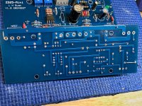
My HGF build has started. Boards are stuffed with resistor values from the latest schematic. Any tweaking can be done down the road after the amp is powered up and healthy.
Initial plan is to use FQA28N15/36P15 FETs and a Micro Audio bipolar SMPS for power. Chassis size is 4U 300mm.
BOM and build guide are a wonderful companion to the build, thanks Lynn🙂.
Initial plan is to use FQA28N15/36P15 FETs and a Micro Audio bipolar SMPS for power. Chassis size is 4U 300mm.
BOM and build guide are a wonderful companion to the build, thanks Lynn🙂.
Attachments

Hello,
What's the current state of affaris on this build? Are there any boards and semiconductors available?
Feel free to PM me.
I checked for the FQA availability and I could only find the N-type.
thanks
What's the current state of affaris on this build? Are there any boards and semiconductors available?
Feel free to PM me.
I checked for the FQA availability and I could only find the N-type.
thanks
birdbox is fantastic to deal with
https://www.diyaudio.com/community/...-amyalice-holy-grail-r21.418639/#post-7813987
https://www.diyaudio.com/community/...-amyalice-holy-grail-r21.418639/#post-7813987
I see that the current pair of fet to get are an ixys and ONsemi combo. How easy to find a match pair?
Well if you peak back a couple of pages to those posted test results, it looks like this circuit is actually a fine performer without the tight matches, particularly into a 4 ohm load.
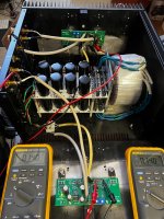
I finally had the time to build my version of the Holy Grail Follower. I had stuffed the boards earlier this year, then May, June, July, September, came and went, 2 hurricanes in October and I finally have the time!
I wanted to repurpose a chassis and power supply as I usually do.
Along the way I managed to mess up, then trouble shoot, fix my screwup.
So, assembled the left channel on the heatsink, drilling new holes to be tapped, wired it up and it biased up no issues at all. The bias set at .140 VDC and the offset was very touchy, but managed to get it to 0.
All was good, I rushed through the right channel assembly and I didn't check the output transistor for continuity with the heatsink and sure enough when I powered it on again I saw smoke! Shut it down, pulled the output devises tested them, they were good. Checked R1 and R2 they were open on the N side, replaced them with my 2 remaining .220 ohm resistors.
There was a small shaving under the N transistor's pad that poked a hole in the Keratherm Insulator.
Cleaned the surface again, new Keratherm, resoldered the transistors and mounted the board. Checked for continuity between the transistors and the heatsink, this time all good!
Powered it up, set the bias, zeroed the output. Both channels working as advertised! put the cover on, hooked it to my Quads and music is playing. After an hour the heatsinks are warm, not hot. Checked the output offset, -.005 on both channels. Checked the bias, it had climbed to .148 both channels, good enough.
I am enjoying this amp very much! Thank you Lynn.
Rush
Attachments
- Home
- Amplifiers
- Pass Labs
- The Holy Grail Follower Output Stage