Building the jfet version. I am getting high voltage to the led bank closest to the V+ terminal. just flicking the power switch I see 13 plus volts and climbing. It appears my Irfp150 is fine and r7 is 3.3k ohms. Any ideas?
Update, I had that bank of LEDs in backwards. It will bias properly but I still have 23 volts going to the single led power indicator now
Update, I had that bank of LEDs in backwards. It will bias properly but I still have 23 volts going to the single led power indicator now
Last edited:
I don’t think I understand or see if you have a question.It will bias properly but I still have 23 volts going to the single led power indicator now
V+ should be about 23V, and it should be connected to R13 which limits the current to LED7. If LED7 is oriented properly it will light up. If not, flip it or replace it if it is already correctly oriented (anode connected to R13 and cathode connected to ground). If it is too bright, try R13=20K or higher.
Anode of LED7 is typically the long lead and cathode is the short lead. If in doubt, test it using a DMM or transistor tester.
LED7 serves no purpose in the circuitry other than being an indicator light.
Best,
Anand.
Thank you, I rushed my post, I went through the schematics like you posted. My problem was that I installed the one bank of LED's reverse polarity. Then due to my lack of basic understanding of electronics I was confused that I was getting 23v on either side of R13. once I installed LED7 it shows 1.7 volts after R13. Off to cook and set final bias and dc offset

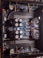
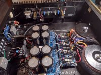
I originally installed a F6 clone board I bought off Canuckaudio mart in this repurposed chassis. From day one the single antek transformer I used had an audible hum in the speakers and at the actually transformer itself. I tried changing out the bridge rectifiers and the cap banks trying to fix the problem. I then traded out the single antek for dual smaller triads. I tried a different grounding scheme, and still it hummed. I thought I would try the these reworked F6 boards to see if that helped anything and it still hummed. So redid the power cord and switch, basically removing the front factory switch and just using a switch on the rear. So far the hum is completely gone. I have limited understanding and try to look at pictures people post in these threads to help with my builds.
Attachments
I've built the F6 and like it. A few questions which have probably been asked previously.
Is there an upgrade/mod to take the power output up to closer to 50 watts RMS?
The input gain or sensitivity is intentionally very low, not sure why, perhaps to keep noise low, but- is there a means of increasing it so I need not run a pre-amp volume in the 12 to 3 range when driving the amp?
What's the best means of running LED's through the faceplate so its easy to know when the amp is on/off? Can I for instance take the two red LED's on the boards inside the amp and run them on extended lengths of wire and use them for this purpose or is there a better means of accomplishing this? I need not have two "power" leds through the front face and one would work fine but it also wouldn't be an issue if there were two.
What other upgrades have been used successfully to beef up output etc. Larger Toroidal transformer (mines the 400v one), different output devices, different power supply, mines the 24v one etc. ?
thanks much !
The F6 was originally introduced at the Burning Amp Festival of 2012. Nelson does a better job of explaining the design decisions than I. Suffice to say that the input gain of 15dB is a choice based on the amount of feedback used to achieve his goals for distortion and output impedance.
The F6 has evolved since 2012. The original output devices are no longer available. It became common to use readily available IRFP240. I chose to use the FQH44N10 when I built my first one. Since that part has also become difficult to find, I have switched to recommending the IXTQ75N10P, and am also investigating the IXTQ36N30P. The higher transconductance devices sound great, and deliver a lively sound when running at higher bias current. Try 1.5A up to 1.6A.
The F6 does well into speakers of lower impedance, increasing its power output somewhat more than other First Watt 25W class amps. The simplest way to get a little more power out of this amp is to increase the rail voltage by using a power transformer with higher voltage secondary windings. Try one with 20V.
Thanks for the info! So I can and will order four of the IXTQ36N30P. from mouser and replace what I have there now - I think they are IRFP240 as I built this in either 2019 or 2020.
Do you have any specific advice on the part number for an upgraded transformer with higher voltage secondary windings of 20V ? I'd order this at the same time.
Thanks much!
Do you have any specific advice on the part number for an upgraded transformer with higher voltage secondary windings of 20V ? I'd order this at the same time.
Thanks much!
Meant to ask about best/simplest way to add power on indicator LED (one or two) to the front face plate. Can I extend wires from the two red LEDs that are on the boards currently and sink the LED's thru the faceplate, running leads from them back to the board mounting points where they're currently hard wired? Or is there a better solution?
thanks
thanks
Sure, run wires for the power on indicator LEDs from the PCB up to the front panel.
The Antek parts would be AS-3220 or AS-4220.
The new PCBs have extra V+, V- and GND connection points. These are intended to support motor run capacitors on each channel. Look for CBB60, 250V around 50 uF or higher.
The Antek parts would be AS-3220 or AS-4220.
The new PCBs have extra V+, V- and GND connection points. These are intended to support motor run capacitors on each channel. Look for CBB60, 250V around 50 uF or higher.
This could be a fun project, this coming winter. The Jensen transformers arrived yesterday in great shape. 🙂👍

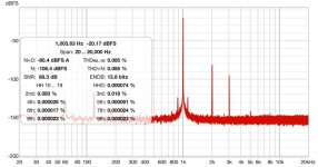
Just finished the build and testing with REW, and I see that I'm getting much higher second and third order harmonics than I had with my F6 from DIY-Audio. The F6 from DIY-Audio uses the Jensen transformer and IRFP240 MOSFETs; the F6 Diamond uses the Cinemag transformer and IXTQ75N10P MOSFETS; both are on the same +-22V power supply and biased to 600mV across R2 and with the same test setup: running 1 watt into 8 ohms with a 1 khz signal. Green is the F6 from DIY-Audio, and red is the F6 Diamond. Not sure where to start troubleshooting, so any pointers are appreciated.
Attachments

Why do believe it is necessary to troubleshoot this build?
How does it sound while playing music?
How does it sound while playing music?
Yeah... I'd look at the grounding, and wiring in general... It wouldn't hurt to check the output (loaded output, with and without input signal present) for oscillations... broad spectrum.
Of course, the photos would help immensely, so that we do not have to hunt in the dark...
Of course, the photos would help immensely, so that we do not have to hunt in the dark...
It sounds fine to me, so maybe "troubleshooting" is the wrong word. It's a more a question of learning. I'd like to understand why my F6 Diamond has higher second and third harmonics than my F6 from DIY Audio. Also, the non-harmonic spikes, which is especially puzzling to me, since I used the same power supply and everything else connecting to/from the board in both cases - just swapped the two boards in and out.
As I understand it IXTQ75N10P MOSFETS have higher transconductance than other mosfets, so they naturally have higher H2. I will let the experts chime in!
Edit: check this post
Edit: check this post
My advice is to read the F6 talk by Nelson here. You will see how he discussed output degeneration resistors and input degeneration resistors. You will also see that Tungsten specifically implemented output degeneration changes to get a second harmonic level that he likes with his system after I am assuming several experiments. And not to mention these are different N-ch Mosfets ((the 75N10P has higher transconductance)) than the diyaudio version which used the IRFP240 . And both are different from the original SJEP power JFETs discussed in Nelson's F6 talk.
Although the use of Cinemag or Jensen phase splitting transformers along with the Austin buffer input stage have low distortion overall, the dominant distortion element here might be the output stage including the Fets themselves and the potpourri of degeneration resistor choices. So experiment away and let us know what you find.
Best,
Anand.
The F6 has a remarkably simple circuit, which offers many possibilities for tweaking by the more adventurous builder.
The boards I have presented here represent a set of choices that I have made over the last couple years to create an amp that I really enjoy listening to. I started using higher transconductance FETs at the very beginning, with a set of FQH44N10. I also built a dual mono PSU that supplied +/– 26.5V and ran with 1.7A to 1.8A of bias current. The higher bias meant having to leave the amp on for a long time before it reached thermal equilibrium. That led to the use of the green LEDs in the voltage reference for the bias circuit. Having those LEDs incorporated into the PCB has improved the thermal settling time further to the point where 45 minutes or so is sufficient.
Newer FETs have become available since the 44N10s are no longer manufactured. The IXTQ75N10 have proven to be a viable alternative. I would also suggest trying IXTQ36N30P or FQA28N15, depending on what you can find. The store is now selling IRFP048 (when they are back online), which were also suitable, though I found the other parts had a more dynamic sound. The bias current may be adjusted from 1.4A all the way to 1.8A depending on the thermal capacity of the chassis. Different voltages and current have an impact on the sound of the amp.
The source resistances are also a means to affect the harmonic content of the output stage. I have included options for tweaking the source resistance of the upper FET relative to the lower one, as this seems to provide an effective lever for altering H2. I also recommend making use of the extra wire mounting holes for V+ GND and V– to install motor run capacitors on each channel. These give a noticeable improvement in sound, especially when using a shared main PSU. The motor run caps I use are CBB60 style, 250V of 60uF or higher, depending on available space inside the chassis.
- Home
- Amplifiers
- Pass Labs
- The F6 Revisited