
Donaldspace:
I believe a correction to your BOM is needed: the 100R 3W CPF3100R00FKE14 resistor should be part number (or "Customer #") R3, not R4.
Regards,
Scott
I believe a correction to your BOM is needed: the 100R 3W CPF3100R00FKE14 resistor should be part number (or "Customer #") R3, not R4.
Regards,
Scott
Folks:
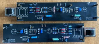
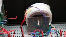
Please forgive my overabundance of caution, but are the CMOQ-4LPC transformers properly oriented in the photo below? Oriented that way, the transformers' pins fit neatly into the pcb vias for T1 but the pin labeling for T1 on the pcbs appears to be 180 degrees off from the transformers' datasheet (https://cinemag.biz/output/PDF/CMOQ-4.pdf). I trust the via positioning more than the pin labeling on the pcbs, but figured it didn't hurt to ask.
Thank you,
Scott
Attachments
C2 and J1 are sorta misaligned, two holes producing one pad
rest of them are almost 100% aligned, so when you superimpose them, pads are perfect
rest of them are almost 100% aligned, so when you superimpose them, pads are perfect
ZM & TungstenAudio:
Yes, the pins on the Cinemags I received needed a little love to fit onto the pads, but they will slip in. My point was that the CMOQ-4LPC datasheet shows that pin 1 is at the lower left corner when looking at the top of the transformer (with the "CMOQ-4LPC" lettering at the top right). However, the pcb labels indicate that pin 1 is at the top right corner. Hence my uninformed confusion.
In any event, thank you for the prompt feedback!
Regards,
Scott
^ Hi Scott -
I've had over 1000 CineMag transformers pass through my hands. Short version... sometimes the lettering is one way... sometimes it's the other. When I pair them for kits, I try to make sure that both transformers in the kit have the same lettering orientation.
The only definitive way to know which pin is pin 1... is by looking at the pins.
Your question is a good one... just don't go by the lettering.
Edited for clarity - Iron Pre kits...
sometimes the lettering is one way... sometimes it's the other
yup
pin 1-2 is smaller pitch than for rest
clear from dtsht
sometimes the lettering is one way... sometimes it's the other.
An excellent point, well taken. Thank you for the explanation. My intention wasn't to call anyone out -- I was concerned about mis-orientation.
Thank you!
Regards to all,
Scott
Oh gosh no. I didn't think you were calling anyone out. It's easy to understand the concern. I've had the same concern myself. It was only after a panic of my own in the not-too-distant past that I noticed that the lettering isn't always the same.My intention wasn't to call anyone out -- I was concerned about mis-orientation.
Cheers!
Patrick
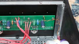
No smoke yet. I'm wondering if changing the output transistors to the FQA28N15 might be a good idea. They're slated for obsolescence but still available. SOA looks better, and I don't see anything else that would be a detriment to the circuit...
Thanks for the error report, Scott. Here is the updated BOM. I suspect that the above mentioned output transistors would not need the higher bias supply voltage fo the IXTQ75N10P outputs.
A nagging question in the back of my mind is what incompatibilities would using the Exicon Laterals present? Their pinouts are different, and I wonder what would have to be done about the low transconductance... The negative thermal coefficients would be good, though.
A nagging question in the back of my mind is what incompatibilities would using the Exicon Laterals present? Their pinouts are different, and I wonder what would have to be done about the low transconductance... The negative thermal coefficients would be good, though.
Attachments
I like the looks of the FQA28N15 for the F6 and other amps (F5m). They definitely have a SOA that is better suited for higher voltage F6 implementations. I bought a few to try after doing a power transformer swap in my F6. Target rail voltage will be just under 30V after a cap multiplier PSU.
I need to acquire another pair of CineMags. These are magic in the new Diamond PCBs.
I need to acquire another pair of CineMags. These are magic in the new Diamond PCBs.
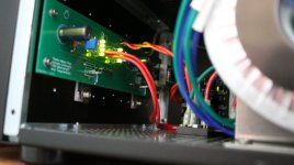
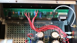
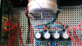
My rail voltage with the Antek 24V transformer was right at +- 30VDC. It just keeps sounding better... My build included a 4 green LED series intead of the 3 green LEDs. Also, these are the first version boards, with the Zen Mod adapters for the Cinemag transformers to fit the boards. I still haven't installed the front panel yet so the picture is around the transformer, a 300VA Antek AS-3224. Thanks for the help and inspiration. Sounds GREAT!
Don
Don
Attachments

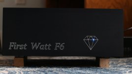
"I'm ready for my closeup, Mr. Demille"
Attachments
-
 IMG_0040.JPG166.4 KB · Views: 192
 -
 IMG_0023.JPG321.3 KB · Views: 198
 -
 IMG_0025.JPG375.1 KB · Views: 179
 -
 IMG_0026.JPG266.9 KB · Views: 174
 -
 IMG_0027.JPG266.8 KB · Views: 180
 -
 IMG_0028.JPG222.9 KB · Views: 163
 -
 IMG_0030.JPG279.9 KB · Views: 169
 -
 IMG_0032.JPG376.4 KB · Views: 165
 -
 IMG_0033.JPG328.3 KB · Views: 189
Just make sure you don’t mistake the red wire.. from the other red wire.
Thanks for the pictures, they really help when putting our own projects together. Mine is almost done. How did you do your grounds? Cl60?"I'm ready for my closeup, Mr. Demille"
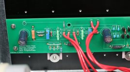
T.A. I have this HUGE spool from Boeing Surplus. Its AWM 105 degree C 16 Ga. I sometimes use a Sharpie to mark both ends of a wire to identify it when installing the wires. One black ring vs. 2 black rings, etc. I didn't do it on this build since it was a one wire at a time assembly.
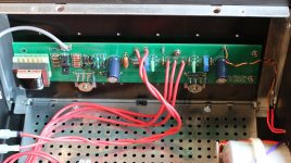
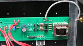
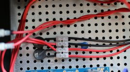
#gsrchrisu, My grounds use the 6L6 recommended CL60s. The ground lift was at the rear of the chassis from the PSU board ground to the subplate with the safety earth at the same place. See the crummy picture. In spite of not twisting the pairs, there is absolutely NO hum or noise. I just routed the wiring as close to the chassis/ground as practical.
The LED in the front panel is through a #60 wire size drilled hole in the panel, counterdrilled with a .111 drill to push the LED in. I think it adds a little artistic flair to the project.
Attachments

Last edited:
Can someone explain the bias setting to me? I am measuring mv between R1 and R*. I am sitting at approx 700mv with about 4 or 5mv of dc offset. Everyone appears to mention bias in amperage on this thread. What mv setting should I be aiming for with a F6 diamond board, irfp150's. My transformer has 18v secondary's with about 23v dc at the boards if that matters. Thank you(pretty sure this is a math thing that I am not fully understanding)
- Home
- Amplifiers
- Pass Labs
- The F6 Revisited