True, unzipping the attachment reveals a folder that contains a second ZIP archive that can be presumably sent to a fab house to make PCBs.
I have a pair of CineMag CMOQ-4LPC transformers that I need to hear in my F6. The current iteration has been sounding sublime lately with quite a few of my favorite recordings. Spooky is the word for the imaging, and musically involving overall. This is the best I have heard from my Vandersteens so far.
I have a pair of CineMag CMOQ-4LPC transformers that I need to hear in my F6. The current iteration has been sounding sublime lately with quite a few of my favorite recordings. Spooky is the word for the imaging, and musically involving overall. This is the best I have heard from my Vandersteens so far.

Yes TA, the second zipped file is OK. Good to hear your thoughts so far with the Jensen's on board. Look forward to your comments if you do install the Cinemag's.
attached zip file is not having Gerber in name
it is containing shown graphical files, plus second zip file which is having Gerber in name
it is containing shown graphical files, plus second zip file which is having Gerber in name
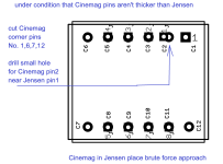
One can fit the Cinemag direct to the F6 pcb with a small mod as detailed below without the need of a daughter board:
1. The Cinemag has 12 pins against the Jensen which has 8 pins.
2. Pins 1,6,7 and 12 on the Cinemag are not used and not connected to the windings.
3. One needs to drill a 1mm hole that is 0.005" or 1.27mm outside of the Jensen pin 1 on the pcb for the Cinemag pin 2 - that is the one with the square land.
4. Carefully sit the Cinemag over the holes so that Pin 5 of the Cinemag lines up with pin 4 of the Jensen hole, similarly pin 8 of the Cinemag will line up with pin 5 of the Jensen. Then you can mark the position of the new hole on the pcb with a fine marking pen for the Cinemag pin 2.
5. Drill a new hole where you have marked (1mm dia or 0.04")
6. Carefully snip off pins 1,6,7 and 12 flush with the Cinemag former. Don't cut any of the other pins!!
7. Now the Cinemag should drop neatly into the holes.
8. Solder all pins, you might just have to bridge the Cinemag pin 2 to the Jensen pin 1 land.
9. Job done, both transformers are the same size within a mm so the Cinemag will fit OK.

I asked Dave Slagle (Intact Audio, US) about winding a pair of equivalent ones and the cost was 'rather high'. Their Txr Volume Attenuators are very good indeed....

Oh please do share schematic so we can follow along! Perhaps new thread if you like…
Best,
Anand.
Best,
Anand.
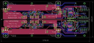
Looks like it has a cascoded JFet front end, using ZM's favorite surface mount devices. Common with other Bablefish designs by the Wiley One.
Love to see it here as yet another revisitation of the marvelous F6.

Love to see it here as yet another revisitation of the marvelous F6.
pretty much trivial regarding FE - already seen 3+3pcs of 2SK2145 same sex JFet buffer feeding two primary sections in series, then one secondary modulating one output mosfet
difference in OS being - again seen already - 0R11 combo in each rail as sense resistance, with optos translating that to governing bias voltages up and down
(common) helper CCS to bring optos in conducting region
I mean - nothing new under the sun,, but I'll leave details for time of actually having pcbs made and populated and confirmed with all measurements
bummer is - I already have entire line of populated Drek, "just" waiting for "when?!?" bench time
If your Babelfish F6 boards turn out fine after testing ZM, I will buy a pair with your 2SK2145 fets loaded. Will be keeping an eye on your progress and will be in touch down the track.

- Home
- Amplifiers
- Pass Labs
- The F6 Revisited