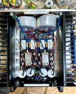
I have been postponing the transistor matching for my new Stasis OS boards. I have four tubes of parts to match for two different builds. The fun part for me was building the power supply for the smaller of the two chassis. I happen to like doing a little metal work as well. The grounding plates were cut and filed from larger sheets of nickel silver alloy.
Attachments

Looking good there TA, what are you going to use to get the +/- DC rails from this chassis to the Stasis amp chassis?
Nice work TA!
I'm interested in the way you hold your transformers in place.
Is that a rubber stopper compressed between a pair of washers to expand in the center of the donut? This creates enough holding power for a heavy trafo?
I'm interested in the way you hold your transformers in place.
Is that a rubber stopper compressed between a pair of washers to expand in the center of the donut? This creates enough holding power for a heavy trafo?
This will be a single chassis build. I drilled and tapped mounting holes for the 8 deep OS boards. Each board has three ground wire mounting holes, all of which will be used and collected back at the channel grounding plate.
I use strongtie angle brackets for mounting the big transformers. A hardware store item used normally for tying pieces of lumber together. I have found a snug fitting rubber stopper (or two) has plenty of holding power when compressed by the mounting bolts. Note that the mounting bolts are nylon to ensure there is no way to create a shorted turn.
I use strongtie angle brackets for mounting the big transformers. A hardware store item used normally for tying pieces of lumber together. I have found a snug fitting rubber stopper (or two) has plenty of holding power when compressed by the mounting bolts. Note that the mounting bolts are nylon to ensure there is no way to create a shorted turn.
And here is how I fared out....OK, I have checked the matching on the KSA992FBU and KSC1845FTA transistors I have here.
For the KSA type, the min Hfe was 462 and max was 520. For the KSC type, the min Hfe was 408 and max was 456.
Out of all that, I got 462 & 466 for KSA and 456 & 456 for KSC for one channel - that is 2.3% match. For the other channel I got 467 & 469 for KSA and 455 & 455 for KSC - that is 3.1% match.
While I was at it, I also checked the Toshiba TTC004B and TTA004B
For the TTC type, the min Hfe was 175 and max was 245. For the TTA type, the min Hfe was 183 and max was 247.
For the left channel I picked TTC at 221 and TTA at 221 - perfect Hfe match.
For the right channel I picked TTC at 222 and TTA at 225 - 1.4% match.
Let's see how Vunce goes with his matching, for all types tested it was easy to get multiple pairs prefectly matched N to N and P to P. It is the N to P matching that is hard to get perfect. I tested about 50 of each of the 4 transistor types using a Peak DCA75 pro tester.
First batch of 40 KSA992's Hfe range was 417 to 440
Second batch of 30 KSA's range was 369 to 415
Batch of 50 KSC1845's Hfe range was 338 to 397
This is what I got:
Chan#1 KSC 384 & 388, KSA 385 & 386
Chan#2 KSC 393 & 397, KSA 395 & 395
Not too shabby 😉
(Also used Peak DCA75 pro)
I am looking forward to the listening impressions. Give the new boards at least a day of power on before serious listening. Then a couple more days to enjoy the sound after everything has had time to break in.
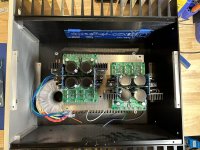
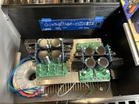
Planning stage of chassis layout tonight.
This configuration would use a pair of Antek AS-3225 trafos mounted at the front of chassis flat on the base.
The PSU boards are mounted on a raised platform, the soft start is underneath in line with the AC inlet module.
The chassis size is 5U x 400mm, the F6 boards are not centered but mounted two fins towards rear. Mosfet mounting hole is 60mm up from base.
Would this be an acceptable distance between the Jensen transformers and power trafos?
Attachments
Probably. If not I have little sheets of mu metal I can send you.

I would say that would work Vunce, but the mu metal sheets wrapped around the Jensen's wont hurt at all.
Nelson, do you use the mu metal on the Cinemag's in your amps?
Nelson, do you use the mu metal on the Cinemag's in your amps?
Looking at the older M2, the pic shows a total shielding box encasing the transformer on the pcb. For the pics I found of the SIT3, it looks like the bobbin is covered with a black shield - which I assume is the mu metal wrapped around the bobbin.
@TungstenAudio
https://www.diyaudio.com/community/...r-in-a-crc-power-supply-r21-ps-module.376003/
And before you ask, this transforms your LT4320 CRC based supply into a high end regulated Class A supply, but with one caveat (currently): The MOSFET used in the regulator circuit is currently unobtainium/on back order due to COVID supply chains.
Plenty to read on that thread.
Best,
Anand.
Here you go! Don't get too excited. Tricky to find device on there.!
https://www.diyaudio.com/community/...r-in-a-crc-power-supply-r21-ps-module.376003/
https://www.diyaudio.com/community/...r-in-a-crc-power-supply-r21-ps-module.376003/
Thank you for the link. (Both of you) I was suspecting some sort of gyrator simulation of an inductor; this looks like more than just that.
Very interesting.. Glad to see you are still using a decent amount of capacitance with the regulators. High end amps need energy storage.
I’ll move forward with the proposed layout, fire up the garage heater🥶
The F6 Diamond and another low power class A amp will both use these power supplies. Took a looong time to gather the parts for the R21 modules, so first time they will be put in service for me.
The F6 Diamond and another low power class A amp will both use these power supplies. Took a looong time to gather the parts for the R21 modules, so first time they will be put in service for me.
- Home
- Amplifiers
- Pass Labs
- The F6 Revisited