Looks like we have some very special F6 Diamond amplifiers in the making.. Matched transistors, regulated power, oh my!
😉
P.S.
I did a silly thing yesterday and reserved a pair of Cary Audio SLM-100 100W tube monoblocks on layaway for the new year. My only other good tube amp is a modified Dynaco ST-70. I need (want) a good tube reference amp to compare with my First Watt builds, the Aleph J and F6 in particular. The Cary monoblocks just popped up at one of my local boutique audio shops. Each has a set of four KT-88s that have been carefully matched and biased. Still love them glowing power devices.

Hey TA, enjoy the Cary amps, hope you got them at a Christmas sale price. I found some time today to start loading up a pair of Diamond Buffer pcb's. I have fitted all the resistors and then the two trimpots - which prompts a question, did you set the 2 pots to any value or at either end of their range before powering up?
Now a couple of comments (and in no way is it a criticism) after loading up the passives.
1. Resistor R22 is silkscreened upside down on 1 of the pcb's, the other channel board is OK.
2. Resistor R1* on the same pcb is silkscreened as R14 for the 1R//0R1, again the other board is OK.
3. Silkscreening on the other channel pcb for U3 is obscured, the 1st pcb is OK.
4. Maybe increase the silkscreen lettering size for the TO92 transistors and the V ref TO92 - it is a bit small.
5. Remove Zeners Z1 and Z2.
6. If you or Mike were to revise the pcb, then add parallel pcb lands for the resistor R1*, rather than piggyback resistors.
7. Again if revised, add the second pin next to pin 1 for the transformer mounting so one could use either the Jensen or Cinemag transformers.
Just thought I would bring those to your attention, obviously all are only cosmetic and don't affect the operation of the board in any way - just to keep in mind for any future revision.
Cheers,
Gary.
So I have been planning on redoing the PCBs a bit. I addressed the points 1-5. Tungsten is on the same page regarding the Zeners.
Done 1. Resistor R22 is silkscreened upside down on 1 of the pcb's, the other channel board is OK.
Done 2. Resistor R1* on the same pcb is silkscreened as R14 for the 1R//0R1, again the other board is OK.
Done 3. Silkscreening on the other channel pcb for U3 is obscured, the 1st pcb is OK.
Done 4. Maybe increase the silkscreen lettering size for the TO92 transistors and the V ref TO92 - it is a bit small.
Done 5. Remove Zeners Z1 and Z2.
Regarding 6, that is up to Tungsten.
Regarding 7, I plan to redo the Diamond boards to take the Cinemag and Jenson transformers the next time I have a free moment. I need to talk to the store to make sure I am not stepping on their toes regarding a regular F6 with the Cinemags. I don't know what their plans are.
Let me know if anything else pops out at you and I can adjust things.
Hi Gary,
Before powering on for the first time, I open both trimpots one turn counter-clockwise from their initial midpoint setting. This gets the bias current close to registering as a voltage across R2. Then I begin opening each pot an additional turn at a time as the heatsinks start warming up. I measure offset across the speaker terminals.
We are keeping a list of things to tweak for the next PCBs. Schedule is TBD. Thank you for your observations.
Edit: See above
The Cary amps were at a reasonable price for used gear with a known provenance - one shop, one previous owner.
Thanks for the quick reply Mike and TA. From looking at the new pcb silkscreen you show in post #243 - I would still increase the TO92 lettering - maybe move them outside the TO92 outline to achieve that. Your point about the dual transformer mounting is noted. Once revised I would add a label to the board silkscreen denoting Rev.1 or similar.
Maybe one other point to think about would be to add the provision for 2 and 3 way PCB terminal blocks in parallel with the +/GND/- and loudspeaker output lands - so people could choose either connection, (screw terminal or solder the wire).
TA, I would add my point 6.
The pot adjust procedure is noted, thanks.
Last edited:
My observations on R1*
The mounting holes appear to be smaller than those for R1 and R2.
Having parallel lands looks feasible, perhaps easier if they are under the main outline of R1*. This would allow separate mounting of the extra resistor, with bent leads.
Note the extra small holes under V+ GND V-. These are for wiring motor run capacitors, or similar. The main holes allow 14ga wire; smaller holes are for 20ga wire.
R1* holes on one of the pcb's appears to be smaller - they all look OK on the other one.
Perhaps also with a revision - mark one pcb LEFT and the other RIGHT on the front silkscreen..
Also, for the motor run caps (if using) there should be an added 2nd hole for 2 GND lands.
TA, you seem to have done well with the Cary's - just had a quick look at a few reviews - all rather stellar with not a bad review in sight.
I am always in favor of terminal blocks or Gaston’s for all external connections: power, grounds and output, indicators (not relevant here).Maybe one other point to think about would be to add the provision for 2 and 3 way PCB terminal blocks in parallel with the +/GND/- and loudspeaker output lands - so people could choose either connection, (screw terminal or solder the wire).
Yep, the pad size on R1* reverted to the original footprint size when I retitled it. Fixed:


So I like soldered connections. I think they are more reliable and I feel that soldering a wire end is very easy so long as the pad locations are accessible.
I could do this:

Is that kind of Janky?
I was going to but then thought it was easy enough to determine. Hold the PCB so the transformers are at the back and the inputs are on top.Perhaps also with a revision - mark one pcb LEFT and the other RIGHT on the front silkscreen..
That is a good point. Each cap will need it's own gnd connection:added 2nd hole for 2 GND lands.
I am always in favor of terminal blocks or Gaston’s for all external connections: power, grounds and output, indicators (not relevant here).
So I like soldered connections. I think they are more reliable and I feel that soldering a wire end is very easy so long as the pad locations are accessible.
That would be neat but there is a big chunky trace there. In order to stack them I would have to make more verticle space for the trace as well as the resistor. So that would mean moving the whole diamond buffer up and redoing a lot of the routing.Having parallel lands looks feasible, perhaps easier if they are under the main outline of R1*. This would allow separate mounting of the extra resistor, with bent leads.
I could do this:
Is that kind of Janky?
I understand you favoring soldered connections. When I look at my attempts to do initial assembly and then servicing/tweaking, it does make it easier when using terminal blocks or fast-in’s. Not my design implementation, though, so I can’t complain! Thanks to you and TA for all your hard work.
"Janky" - that must be a local Vermont phrase Mike, the R1* solution is OK with me.
Terminal blocks for power etc, are convenient.
Larger lettering for the TO92's.
Terminal blocks for power etc, are convenient.
Larger lettering for the TO92's.
The proposed not-too-janky parallel lands for R1* are what I had in mind. I could see that offsetting the extra mounting holes would cause a lot more re-wiring and didn't want to push for that.
I also prefer soldered connections for the power wires, even when I am the crazy guy taking the boards out of the amp multiple times to try different tweaks and what-not. The only amps that I use terminal blocks in are my ACAs, and that is because those PCBs didn't support good solder connections. (Not the store ACA boards, a different set.)
I also prefer soldered connections for the power wires, even when I am the crazy guy taking the boards out of the amp multiple times to try different tweaks and what-not. The only amps that I use terminal blocks in are my ACAs, and that is because those PCBs didn't support good solder connections. (Not the store ACA boards, a different set.)
Nice score on the Cary mono's TA! The warm glow of the KT-88 octet will be perfect for winter listening.
I populated all the resistors on both boards and did notice a few stencile "imperfections", but nothing thats not self explanatory.
I do like to use connectors for wiring, but this is a highly debated topic and do not want to derail this thread. Put it this way, I saw how the wire connections were made on these boards right from the start and still chose to build them . Thanks Fellas!
I populated all the resistors on both boards and did notice a few stencile "imperfections", but nothing thats not self explanatory.
I do like to use connectors for wiring, but this is a highly debated topic and do not want to derail this thread. Put it this way, I saw how the wire connections were made on these boards right from the start and still chose to build them
. Thanks Fellas!Connectors... ya I'm not looking for debate either.. but what I do is just look at each situation and determine what seems to make sense. For high current (PS rails, etc.), I solder or use some serious connectors (XT60's from the hobby industry). Less demanding stuff I've been using FASTON's, terminal blocks, or just soldered if the connection is within reach. Doesn't take long to heat up an iron. Connectors do make it nice for quick swap-outs to try different configurations, do some upgrades, or whatever..
I used to mess with terminal blocks and connectors but realized that they don't really save that much time and are not reliable.
Looking at the Pass Labs products, supply and speaker connections are all soldered. All the inputs are soldered as well. There are ribbons from the front stage to the output stage. However, that is simply because there are so many connections to be made and the amps have to maintain some amount of modularity in order to be easily serviced.
Looking at the first-watt stuff, everything is simply just soldered. There are few enough connections that it is easy enough to do. Just like on our projects here. 🙂
I think if you want to have the more modular approach, I would use some sort of connector with a wire lead hanging off of the end. This might even be a better approach as you can have a wire set with connectors coming off of the power supply, binding post etc always be the same length. Then the wired connector coming off of the amp board can be tailored to the connectors in the case. The amp board connections are never in the same spot as other amp boards.
Okay, here is a practice run of the Cinemag transformer layout. Feel free to look at it and let me know if you see anything off. I am just going off of Zen Mod's PCB plus the dimensions in the Datasheet. Instead of doing a two hole solution for J1/C2, I just made a slot that should accommodate both.

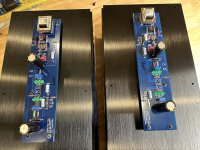
Some more progress....
Heatsinks are prepped and F6 Diamond boards are built, minus the OS Fets.
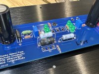
The right channel board has a tight area around C1,6,7 and R3. The Nichi Muse cap is 18mm diameter and is very close to R1, if this resistor gets hot it might be a concern.
@Mikerodrig27, if you plan to remove the zeners, maybe shift the LEDs, trimpot, R4, R9 and R3 down the board a few mm’s that Z1 used to occupy, if that’s possible. That would give some breathing room between R3 and C1. The left channel is good.
What’s progress without porn…😆
Heatsinks are prepped and F6 Diamond boards are built, minus the OS Fets.
The right channel board has a tight area around C1,6,7 and R3. The Nichi Muse cap is 18mm diameter and is very close to R1, if this resistor gets hot it might be a concern.
@Mikerodrig27, if you plan to remove the zeners, maybe shift the LEDs, trimpot, R4, R9 and R3 down the board a few mm’s that Z1 used to occupy, if that’s possible. That would give some breathing room between R3 and C1. The left channel is good.
What’s progress without porn…😆
Attachments

Nice work, again you are ahead of me Vunce.
Mike, that looks good on the dual transformer footprint, I will check the details tomorrow for you.
Mike, that looks good on the dual transformer footprint, I will check the details tomorrow for you.
 .
.- Home
- Amplifiers
- Pass Labs
- The F6 Revisited