I paid $76.20 with shipping and sales tax back at the end of July last year.
CMOQ-4LPC is the correct part number. you call their number to place the order. not posting it here because bots.
CMOQ-4LPC is the correct part number. you call their number to place the order. not posting it here because bots.
I just ordered 4 Cinemag CMOQ-4LPCs last week, and the total was $137.17 US. I have lots of the Cinemag to Jensen adapter boards received from JLCPCB. If someone needs a pair I can probably mail them in a small envelope for $3.00 in the US.
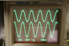
Some pics from the O'scope while hooked up to dummy loads. The first pic is 3.5V PP input (upper trace) and 40V PP just before clipping.
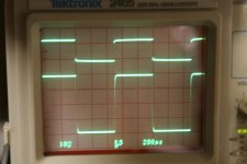
2nd pic is 1Khz Square wave.
3rd pic is 10 Khz square wave.
2nd pic is 1Khz Square wave.
3rd pic is 10 Khz square wave.
Attachments


Next 3 pics are as follows:
1st: 10Khz Square wave with 2.2uF cap. across 8.25 ohm dummy load. Note the input impedance distortion on the upper trace compared to the previous post.
2nd: 1Khz driven at 4.0V PP to show serious clipping. Note the rounded corners of the clip.
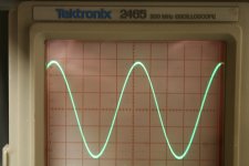
3rd: 1Khz sine wave input 50mv. Nice smooth sine wave, pure class A.
I've listened to it and it sounds perfect. This build used the IRFP240 outputs, 100ohm gate stoppers, 3 green LEDs, 3.3K bias resistors, and input stage per the diamond schematic.
Thankyou to T.A., N.P., and Mikerodrig27 for an enjoyable project.
Next Amp, IXTQ outputs with higher voltage power supply... Should be getting my Pearl 3 Monday so I'll be busy for a while.
1st: 10Khz Square wave with 2.2uF cap. across 8.25 ohm dummy load. Note the input impedance distortion on the upper trace compared to the previous post.
2nd: 1Khz driven at 4.0V PP to show serious clipping. Note the rounded corners of the clip.
3rd: 1Khz sine wave input 50mv. Nice smooth sine wave, pure class A.
I've listened to it and it sounds perfect. This build used the IRFP240 outputs, 100ohm gate stoppers, 3 green LEDs, 3.3K bias resistors, and input stage per the diamond schematic.
Thankyou to T.A., N.P., and Mikerodrig27 for an enjoyable project.
Next Amp, IXTQ outputs with higher voltage power supply... Should be getting my Pearl 3 Monday so I'll be busy for a while.
Attachments
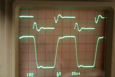

Pretty good behaviour with 2.2uF capacitor || 8.25ohm resistor, especially for 10kHz input. Impressive actually.
Nice little amplifier... Later this year I plan to build the high power version, with +- 30V rails, IXTQ75N10Ps, etc. I'm attaching a pdf of the BOM. De-select the items that you don't need for your build, ie. Q1,Q2, R7,R8, appropriate LEDs, for example. FYI, I used 100 ohm gate stoppers on my build because I had them.
Don
Don
Attachments
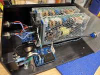
I made my own synch rectifiers for my Burning 3 based on LT4320 and CSD19536KCS Fets from TI. The parts are on top of the board and the 4920 (Keystone) spade conns are on the bottom. IC pin 1 down right. If anyone wants the Gerber Zip, tell me and I'll post them.
K

K
How is this meant to be mounted inside the chassis?
A picture of the board in use would be helpful.
A picture of the board in use would be helpful.
Also missing the required capacitor as far as I can see, which appears in all other designs around here.
Yes, the 0.1 uF cap is essential to power the LT4320. It uses an internal oscillator and charge pump to drive the external Mosfets.
Yes, it was 1.0 uF. My mistake. Ceramic is preferred by the datasheet, and I have also used MMK film with good results.
The choice of Mosfet matters as well. I look for parts with a lower total gate charge, as the LT4320 is actually using a charge pump to drive the Gates. Mosfets rated for 60V Vds are usually easier to drive than those rated at 100V.
The choice of Mosfet matters as well. I look for parts with a lower total gate charge, as the LT4320 is actually using a charge pump to drive the Gates. Mosfets rated for 60V Vds are usually easier to drive than those rated at 100V.
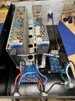
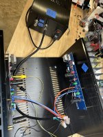
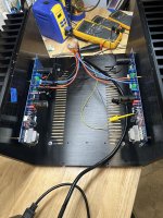
Having the built and ready to go F6D boards on heatsinks sitting on the dining room table waiting for a suitable transformer has been driving me nuts. I just buttoned up an external bipolar psu based on a pair of Meanwell HRP-200-24 smps's and decided to power up the F6D boards. The psu manages to output +/-29vdc with both channels biased at 1.8A. I'll monitor the bias current and offset this evening and then move on to I/O signal wiring. Hopefully first sound this week, Yahoo!
Attachments
Nice work as usual Vunce. From what I have been reading on various threads in the Pass Labs forum here - the Meanwells might be the way to go. Take up less room, easier, cheaper and just about same overall performance as linear non reg supply.
By the way, what chassis is that you show in the pics?
By the way, what chassis is that you show in the pics?
Ah, this should be interesting. There has obviously been some discussion about the use of chassis mount SMPS in the F5m, and other Nelson Pass designed amps in previous threads. I think much lies in the details of the implementation.
These particular units, the HRP series in 200W, have good chance at being successful, and appear to be very similar to the RSP series. So far this looks like a good start, with a well-defined star grounding point. I worked with the RSP series (200W, 27V) in one of my ACA builds, comparing it directly with an otherwise similar ACA with a linear supply that delivered the same internal rail voltage, following supply rail filtration. The two were very close in sound, but the linear supply version had the advantage in bass impact and extension.
This is not meant to dissuade one from working to find a better implementation of a chassis mount SMPS. I simply didn't have the correct recipe for this build. Other projects were calling my name (DIY Sony VFET amp, etc.) and I moved on before further work with that ACA.
I have thoughts about what might constitute a successful implementation and have written some of those in the Holy Grail output stage thread. There it was evident that the only accepted means of testing the suitability of a PSU was using a spectral analysis tool. My experience (as a retired EE) leads me to have a different approach to analyzing a PSU. In brief, I use traditional tools such as distortion and spectral analysis to find what is wrong with a amp design, then I use my ears to determine what is ultimately right.
By all means, proceed, sir.
As an addendum to the above, I had a pair od Meanwell LRS-200-36 units waiting to construct an external PSU for my VFET amp. It was the experience with the ACA that shifted my effort to building a linear supply instead.
- Home
- Amplifiers
- Pass Labs
- The F6 Revisited