With 8R traces set in "gold" and overlaid the without 8R. I slightly moved the Gold version just little to the right so that nothing was hidden...

//
//
 Hey folks, I need to jump in here with a construction question: I’m working on the driver cutouts and realized I am not sure of the suggested way to attach the tweeter and waveguide. … help!! Thanks, HappyJack
You should twist the speaker from the waveguide.
This waveguide holds the speaker and is then screwed to the inner panel. And the front has the same thickness as the waveguide and the hole in which it fits.
This waveguide holds the speaker and is then screwed to the inner panel. And the front has the same thickness as the waveguide and the hole in which it fits.
Attachments
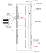
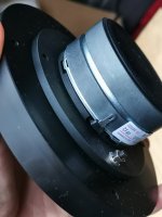
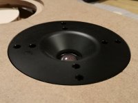
Like JarBar is indicated, from what I can see, mount the waveguide to the tweeter so that it becomes a single unit. Now mount that as a unit into the box. It gives the whole thing the strongest mechanical fit.I am not sure of the suggested way to attach the tweeter and waveguide
Check this measurement plot done with a Microphone.
Thanks for the effort, appreciate it. But some have gone on the jolly wagon a bit too quick. Oh well.
Next step, double the voltage and now use the same 8R resistor in series. Keep in mind that 12 years ago Esa and I agreed that 5:1 should be the minimum, but not much later he was intimating that some benefit could be had with lower ratio. So adding the the same series resistor in series, and comparing it with the measurements you have already done, does that make a difference? Yes I know, the rising impedance will be exposed, but will we see a benefit beyond what could be explained by that? Will there be an improvement greater than expected, maybe by 6dB?
Also, keep in mind that those who have tried that parallel resistor trick were not just listening to a single driver. I have made it very clear that these were 2-Way ho-hum speaker designs that are so boringly common and that they have a rising peak Z somewhere in the critical midrange. Some like this:
The red line is joining the spot checks where a parallel 8R is used. Now it is clear that this is rather different from a single driver and we see that midrange peak hugely flattened out. This is the Revel M126Be speaker and Isaac who added and listened to the result and was gobsmacked, we are still left with the question, what was it that he heard? So we have two additional components involved, the crossover and the tweeter.
Am I to be castigated because I am asking legitimate questions? I am quite certain that what Isaac and others have heard is not delusional.
I have an hypothesis that I am exploring and I am also gearing up to do tests, one of them which is one that I am quite certain has not done before. If successful then it might open the door and see where further to look.
We have gone through a generation where we have believed that the ideal amplifier somehow grips and controls the loudspeaker. Yet speaking with an increasing number of speaker designers, there is a movement towards creation a somewhat isolation between the amplifier and the speaker, and doing this with the way they design and manipulate crossovers. They are simply finding out these things by simply listening to the sounds they are getting. They don't want to go down the current-drive with so-called separates. For active speakers, that is different, especially use current-drive on the midrange. But I know of one designer who did design an active 2-Way speaker system and came across something. The treble did not sound right when connected directly to the tweeter (the high-pass was taken are at the line-level) and described as somewhat steely. They then did what you normally don't do in an active speaker system, they added a resistor, then corrected the level up to compensate, and now the treble sounded sweet.
They found that an amount of isolation improved the sound.
Isolation between the amplifier and the speaker, but not going all-in current-drive.
Let us consider a thought experiment. Instead of making it an 8R parallel resistor, and this time let us use Isaac's Revel M126Be speaker (the Z above) and not a single P17WJ-00-08 driver. Make the resistor 0.1R which is 80 times lower than nominal 8 Ohm of the speaker. Now the amplifier would hardly see the speaker at all, Indeed in the midrange crossover region, it would not be 80 times lower, it would be 210 times less than the load that the amplifier sees. Again, this is very high level of isolation. Especially at the high Z midrange frequencies.
Alas, I don't have an amplifier that can handle 0.1R loads. But I do have one that can do 2 Ohm comfortable, so maybe I should let Isaac try that and use a 3R3 resistor.
Coming back to your first H2, H3 measurement, I am not sure what the equipment you used, but I did look back into the 'vault' and found the below measurement of what was a then newish design from Audio Technology, the 18H52 C-Quenze Midwoofer, still in production. The measurement was taken 03/03/2007, so 16 years ago, with Clio 7 (I have Clio 11 FW now):
As you can see H5 up to 4500Hz. This was a pricey driver. Still is.
Hello All,
I will be away from the bench for a few days. I am traveling to Santa Clara to go to a Audio Precision APx500 software training. This is the first in person tech event I am attending post Covid.
The equipment is a Audio Precision APx555 Analyzer, a Audio Precision APx1701 transducer interface. The microphone that is used most often is a Audio Precision 426M16. The software is APx500.
We are most used to seeing is 2HD and 3HD data in the manufacturers data sheets. The APx500 software will include any Harmonic Distortions you specify. However too many colored line gets way too busy fast. A single Total Harmonic Distortion, green or blue or what ever color line can be plotted on the graphs without 2HD and 3HD being specifically shown.
Measurements made with a Current Sensing resistor are cleaner, less noise. In the end I like measurements made with a microphone, that is closer to a set of real ears listening.
I do not care too much about how this measurement stuff turns out. I do have my suspicions about where it will end up. Those with golden ears and pockets will buy what they want anyway.
Next I will try a series 8R resistor and double the volts.
The Dale Vishay NH-250, 250 watt test resistors weigh more than a pound of butter each.
Thanks DT
Congratulations on your selection for this training and I hope you enjoy the trip. I read a little about your equipment the other day, and the instrumentation amplifier does seem to have held up against the significant variation in current.
And what does a pound of butter weigh?resistors weigh more than a pound of butter each.
waveguide holds the speaker and is then screwed to the inner
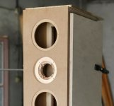
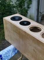
Thanks folks for the guidance. — I just finished the cut out for 1 tweeter and am working on the 2nd one today!!Like JarBar is indicated, from what I can see, mount the waveguide to the tweeter so that it becomes a single unit.
Less than half a kilo.And what does a pound of butter weigh?
Sometimes it helps to visualize a concept. How many cubes of butter does something weigh? It is instructive for me.
Whats a henweigh?
I used to tell my young son that a fully charged uf1000 100volt capacitor stores enough energy to lift your 20 pound dog 2 feet off the floor.
Thanks DT
Lol 😀I used to tell my young son that a fully charged uf1000 100volt capacitor stores enough energy to lift your 20 pound dog 2 feet off the floor.
Some will be surprised at this. More than a pound of air, but less than a pound of lead. Of course measurements can't show the difference, but I can feel it.And what does a pound of butter weigh?
This is the Revel M126Be and it sells for AUD $7500, so it is a premium compact speaker with 6" driver and Beryllium tweeter.

Rear:

Nicely made speaker, as you would expect for the price.
Now this is where some parallel 8R 100W resistors were added and the two Z responses below:

We can see that through the critical mid-frequencies how flat it looks. At those frequencies there is a lot more current going through the parallel resistor, I did a quick calculation, About 71% goes through the resistor at 2KHz and 29% on to the crossover and on to the drivers. The amplifier sees more of the resistor than the speakers, particularly around the crossover point. Is this having a stabilising affect around the crossover. Yes, saying stable may not be the best word, but is is what comes to mind.
Let us look to the current phase angle:

We can see that above 1KHz the phase angle is under 10° deviation from zero degrees.
Of course this all looks very academic... until you listen to it. The difference in sound is not hard to spot and this neat trick, usually with 2-Way speakers like this, it has now been done so many times.
So we have a mystery on our hands.
Personally I think that they way that current behaves has to be a key, this what has to lead to an answer. I am running experiments where you can have the current of the amplifier look very different from the voltage. What is interesting, the closer that we get to a resistor and when we get to using an actual resistor, only then does the voltage and the current look the same. But what good is that, we don't listen to resistors.
My suggestion is that we use amplifiers to test speakers, but we need speakers to test amplifiers. That is the challenge.
As a post script, adding the 8R in series also leads to am improvement. But here you will hear a slightly more mid presence and fuller bass, but also a bit more pure sounding. When we add 8R series resistance, we also get a flatter current phase angle. So it against points to current as being at the heart of this and hence figuring out why.
In the meantime, if you know anybody with a typical 2-Way speaker system that is rated at 8 Ohm and you have some spare 8R resistors lying around (you can get sandcast 8R2 just about anywhere), get them to try it. It is likely they will like it and leave those resistors in place and just enjoy and forget.
Packing and going to Singapore for a break.
PS: The above are actual measurements of the speaker, thank you to Isaac for bringing them around. Isaac follows things here.
Rear:
Nicely made speaker, as you would expect for the price.
Now this is where some parallel 8R 100W resistors were added and the two Z responses below:
We can see that through the critical mid-frequencies how flat it looks. At those frequencies there is a lot more current going through the parallel resistor, I did a quick calculation, About 71% goes through the resistor at 2KHz and 29% on to the crossover and on to the drivers. The amplifier sees more of the resistor than the speakers, particularly around the crossover point. Is this having a stabilising affect around the crossover. Yes, saying stable may not be the best word, but is is what comes to mind.
Let us look to the current phase angle:
We can see that above 1KHz the phase angle is under 10° deviation from zero degrees.
Of course this all looks very academic... until you listen to it. The difference in sound is not hard to spot and this neat trick, usually with 2-Way speakers like this, it has now been done so many times.
So we have a mystery on our hands.
Personally I think that they way that current behaves has to be a key, this what has to lead to an answer. I am running experiments where you can have the current of the amplifier look very different from the voltage. What is interesting, the closer that we get to a resistor and when we get to using an actual resistor, only then does the voltage and the current look the same. But what good is that, we don't listen to resistors.
My suggestion is that we use amplifiers to test speakers, but we need speakers to test amplifiers. That is the challenge.
As a post script, adding the 8R in series also leads to am improvement. But here you will hear a slightly more mid presence and fuller bass, but also a bit more pure sounding. When we add 8R series resistance, we also get a flatter current phase angle. So it against points to current as being at the heart of this and hence figuring out why.
In the meantime, if you know anybody with a typical 2-Way speaker system that is rated at 8 Ohm and you have some spare 8R resistors lying around (you can get sandcast 8R2 just about anywhere), get them to try it. It is likely they will like it and leave those resistors in place and just enjoy and forget.
Packing and going to Singapore for a break.
PS: The above are actual measurements of the speaker, thank you to Isaac for bringing them around. Isaac follows things here.
Hi Alfred
Isaac owns the speakers and brought them around last night and we did the measurements on my Audiomatica Clio V11.45 setup. There is a V12 but I have the Firewire edition and only the newer version has USB. I can get mine upgraded to USB but it needs to be sent to Florence and the whole thing will cost at least $500 and it is fine as it is and there are more V11.45 users out there than V12 w/USB. A lot of professional speaker designers use this and many came over from the extremely complicated MLSSA software. I also have a number of measurement microphones here, main goto is Earthworks M30. But this was an electrical measurement
Link: Audiomatica Website
Aha - I see.
Not so interested in USB versions... more of the electrical hookup for the measurements done. I mean if one would like to replicate them on ones own speakers...
//
Not so interested in USB versions... more of the electrical hookup for the measurements done. I mean if one would like to replicate them on ones own speakers...
//
I don't have any problems with Firewire. I have a Mac laptop with Windows 10 loaded on it and the port (whatever name they give it) works just fine. In my main desktop computer I have a PC Firefire card and also works great. Don't need USB.
Not a difficult measurement, lots of equipment out there could do it.
But we still have a mystery. Whether you add in series of parallel, it does something, but parallel is more effective than series, you need to go up to 18R series and I have heard that as well. Yes, there is a bit of a tonal shift, but not as much as I expected. But the 8R is better at controlling the phase angle.
I have an hypothesis, that this is about isolation and that speakers sound better (or is it the amplifier, or both). A series resistor will do that, but a parallel resistor, isolation is not obvious. But at critical mid frequencies and 71% of the current is going through the parallel resistor and that is what the amp mostly sees. Imagine making the parallel resistor 0.1 Ohm (thought experiment) then 99.5% of the current would go through the resistor and 0.5% of the current of the speaker, the amplifier hardly sees the speaker at all and hence isolation to a high degree is achieved.
We can hear distortion at mid-frequencies that are -80dB (or even better) and that is 0.05% distortion or less. Certainly current-drive has shown stuff in this region. But I am trying to get voltage drive to sound better.
My Clio is worth a couple of grand, but when you have to add other stuff and the cost goes up. I scored a QA403 32 bit analyser (the Clio is 24 bit) and looking forward to using it. I have several testing mics (maybe five), but the best is Earthworks M30 - when you have to do nearfield extreme SPL, that is the mic to use, even without correction it is pretty much flat to 30K and worst is -0.6dB @ 10KHz, so it is essentially rated -/+0.3dB.
When somebody says 'noise' it gets my ear. Did you say how close your mic?
... back to packing...
Not a difficult measurement, lots of equipment out there could do it.
But we still have a mystery. Whether you add in series of parallel, it does something, but parallel is more effective than series, you need to go up to 18R series and I have heard that as well. Yes, there is a bit of a tonal shift, but not as much as I expected. But the 8R is better at controlling the phase angle.
I have an hypothesis, that this is about isolation and that speakers sound better (or is it the amplifier, or both). A series resistor will do that, but a parallel resistor, isolation is not obvious. But at critical mid frequencies and 71% of the current is going through the parallel resistor and that is what the amp mostly sees. Imagine making the parallel resistor 0.1 Ohm (thought experiment) then 99.5% of the current would go through the resistor and 0.5% of the current of the speaker, the amplifier hardly sees the speaker at all and hence isolation to a high degree is achieved.
We can hear distortion at mid-frequencies that are -80dB (or even better) and that is 0.05% distortion or less. Certainly current-drive has shown stuff in this region. But I am trying to get voltage drive to sound better.
Good stuff. Deep pockets?The equipment is a Audio Precision APx555 Analyzer, a Audio Precision APx1701 transducer interface. The microphone that is used most often is a Audio Precision 426M16. The software is APx500.
My Clio is worth a couple of grand, but when you have to add other stuff and the cost goes up. I scored a QA403 32 bit analyser (the Clio is 24 bit) and looking forward to using it. I have several testing mics (maybe five), but the best is Earthworks M30 - when you have to do nearfield extreme SPL, that is the mic to use, even without correction it is pretty much flat to 30K and worst is -0.6dB @ 10KHz, so it is essentially rated -/+0.3dB.
Measurements made with a Current Sensing resistor are cleaner, less noise. In the end I like measurements made with a microphone, that is closer to a set of real ears listening.
When somebody says 'noise' it gets my ear. Did you say how close your mic?
... back to packing...
Hi,
parallel resistor affects amplifier load and amplifier operation. It should not have any effect on the speaker or speaker motor distortion /current as long as output impedance of the amplifier is low.
If the parallel resistor makes sound better, then its the amplifier sound that changes for better. Have you tried if its true for many amplifiers or just the particular one you have?
And as you say this means when you swap speakers its not just the speaker sound that changes but also the amplifier sound.
@see this https://www.audiosciencereview.com/...ing-a-complex-load-by-power-amplifiers.43900/
If the parallel resistor makes sound better, then its the amplifier sound that changes for better. Have you tried if its true for many amplifiers or just the particular one you have?
Let's face it, we must find a way to test amplifiers when connected to a real world speaker and not dummy loads. Yes, it has been tried with a number of different amps.
Tools of the trade, investments, toys or indulgences?Good stuff. Deep pockets?
I am a retired Consulting Mechanical Engineer. I worked for Investment Banks, Hospitals, Research labs, universities and performing art centers. Much of what I did was sort out noise and vibration issues.
One thing that I learned is that scanning electron microscopes do not work well in a ductal moment steel frame building. A truck drives by in the driveway and the building shakes so bad that the field of view in the SEM is useless. A research lab building became a faculty office building. To illustrate the level of vibration: if you placed a picture of water on the 3rd floor conference room table you can see, if you look close, ripples in the water. Yes like the T-Rex caused ripples in the puddles in the movie.
When somebody says 'noise' it gets my ear. Did you say how close your mic?
Yes noise.
The cooling fans in the instruments on my bench make noise. The HVAC fans in the furnace make noise. Sound bouncing around the room and off the walls is noise. I do not like cruse ships or airplanes because they make noise that I can not control.
Microphones have a noise floor. Microphone preamplifiers make noise. Bury your microphone in a plastic bag in 40 pounds of unused cat litter, you may get close to the microphone noise floor. Now take a look at a $5.00 precision resistor, it is much cheaper and much more quite than a microphone.
In the measurement of speaker sound quality Force Factor Modulation is one of the biggest pieces of the total. Force is produced by voice coil current. For a head start I am going to take a close look at current measurements taken from strategically placed Current sensing resistors.
To go along and get along I have been placing the microphone 20CM or 8-7/8inches from the plane of the driver. As called out in Esa's paper.
I have applied a dBrB bias value to match the current resistor measurements to the microphone measurements.
For grins see the attached photo of how the sensing resistor is used and connected by XLR to the analyzer. The Red clip is the hot pin and the Blue clip is the cold pin. A low noise precision measurement tool.
Thanks DT
- Home
- Loudspeakers
- Multi-Way
- The "Elsinore Project" Thread