Hello All,
I am getting a clearer view of how the tire is wrapped around the axle.
First, if the tire was perfect it would still be on the wheel. As previously stated the tire is not perfect and that it is wrapped around the axle.
There is a stated opinion that the problem is possibly related to voltage but most likely "caused" by current. There are several eye witnesses. It was dark and the witnesses may have been under the influence.
The problem is defined as distortion and that the preferred solution is current equalization.
My preference is to take a look at a six pack of the usual line up of potential distortion suspects to determine who shot Jack.
We have the tools to measure voltage, current, possibly visualize and quantify various forms of distortion.
If we isolate a single amplifier and driver we can eliminate many of the possible variables.
Today I ordered several 0.1R low inductance 3 watt wirewound Vishay resistors. On my bench I have 4 Vishay 250 Watt 4R test resistors.
Seems like we are talking of measuring Voltage and Current at multiple locations with and without a 8R resistance in parallel with a Driver Under Test.
If a Voltage amplifier is good at delivering constant voltage to a 8R driver load it should also be equally good at delivering a constant voltage to the same 8R driver in parallel with a 8R resistor. (disclaimer: within the amplifier limits). Why/How would the the current through the 8R driver be equalized by the added parallel 8R resistor? I do not expect to see the measured current through the driver or sound output changing as a result. I will take a close look see for sure.
There is also the discussion that with the 8R Driver in parallel with the 8R resistor the amplifier will be producing twice the Watts with a slightly improved THD+N performance. My Compression Driver tweeters hiss less with a parallel resistor. Yes it is a L-Pad voltage divider / attenuator.
Thanks DT
Last edited:
Hi, yeah, current through driver/speaker would stay the same with same voltage with or without the parallel resistor. Current through amplifier ~doubles because also the resistor draws current, there is two loops in the circuit now with the shunt resistor. Loudspeaker function is not affected by the parallel resistor if amplifier output impedance is very low, which effectively shorts the resistor so backEMF related current is about the same with or without the resistor, it flows thought the amplifier output in both cases as its the lowest impedance path.
Only effect from the parallel resistor for acoustic performance of the system would be how the amplifier behaves and as you note 4ohm load probably means less distortion than 8ohm load. At least some amplifiers I checked list their THD reading with 4ohm load which I assume is the absolute lowest THD number for impressive marketing which means at some other load like 8ohm the number would probably be larger, how much I have no idea. If amplifier THD is marketed to be 0.001% and you measure acoustic distortion of 0.1%, then it doesn't matter measurement wise if the amplifier distortion tenfolds, some other distortion mechanism dominates THD and it would still measure about 0.1%. THD does not correllate with perceived sound quality though, so perhaps the miniscule amplifier THD number matters if it contains some particularly audible distortion.
The hiss, thats probably it. Amplifier noise would be cut in half. I think this would be the most noticeable difference with/without parallel resistor.
Hiss would be cut down with series resistor/impedance as well. Series resistor would affect the backEMF and reduce distortion of the speaker too, which would most likely measure lower system THD with a microphone. Depending on the other crossover components the system frequency response might also be affected for the same reason, effect to backEMF, impedance.
Last edited:
The first question that comes to mind is: does SPL over the full pass- and stopbands measure exactly the same with and without the 8 Ohms R?
Hi, it should unless the amplifier is now working outside its specification. Loudspeaker doesn't see the impedance of the parallel resistor if the amplifier output impedance is very low, so the loudspeaker functions as before, has the same backEMF effects as before. Only thing that changes in the system is amplifier load impedance which affects how the amplifier behaves. For well designed amplifier its hard to believe there was much difference in frequency response of the amplifier between ~4 or ~8ohm load.
I'm no amplifier expert, but I assume the amplifiers are much more well behaved than loudspeaker drivers as they operate in electrical domain only, where loudspeaker drivers have mechanically moving parts affecting as well, another dimension of complexity and variables added on top. I see no reason performance of some amplifiers would change dramatically between 4 or 8 ohm nominal loads if they are designed so, while some other amplifiers it could if they are optimized for one with the cost of reduced performance for the other. Since loudspeaker load varies between say 4-40ohms for any typical loudspeaker then I would say any consumer market amplifier are optimized to handle varying load impedance without much variance to the sound.
Like DualTriode writes the hiss reduces. Amp noise would reduce because ~half of it is wasted in the resistor. I would bet my money on the noise reduction that makes most of audible difference for parallel resistor at the moment. This seems the most logical "big enough" audible difference without actually trying / measuring. I have quite sensitive speaker system and amplifier noise is a problem. I have L-pad and had to buy low noise amplifier to reduce the noise. Its a seriously audible issue. I would claim it only audible difference between current and old amplifier system I had, without doing any AB testing, is noise reduction. It was also the only motivation I had to buy "better" amplifier, better meaning lower noise. Its easy to hear difference and too much noise is distraction. Cutting noise from audible to barely audible, or from barely audible to not audible, would make anyone glad, at least me.
Whats the lesson? If a parallel resistor makes better perceived sound quality it would be indication the amplifier is not as good as it could be 😉 Conversely, if resistor makes no audible difference your amplifier is fine, working as specified and has low enough noise.
Last edited:
sorry, edit time over. And not only hiss is reduced but the mains hum as well, any power amplifier noise. Old amplifier with failing capacitors or poor wiring / grounding scheme could have rather audible mains hum / rectifier noise, which would also reduce with the parallel resistor trick.
It seems the parallel resistor would be easy and practical tool to evaluate amplifier performance by ear 🤔 If sound gets better then its time for TLC, swap caps and clean dirty contacts. Or time to look for better amplifier. If sound doesn't change then there is no particularly audible problem with the amplifier with the speaker system and setup at hand and getting another amplifier might not improve sound that much.
It seems the parallel resistor would be easy and practical tool to evaluate amplifier performance by ear 🤔 If sound gets better then its time for TLC, swap caps and clean dirty contacts. Or time to look for better amplifier. If sound doesn't change then there is no particularly audible problem with the amplifier with the speaker system and setup at hand and getting another amplifier might not improve sound that much.
Last edited:
I think this really summarise your investment in all the current EQ and-what-not peculiarities you engage in - it "rings and it sells". I don't think it is deliberate.That made me laugh, but anti-jitter crossovers has a nice commercial ring to it.
You are so into it that you avoided to bother about "I have seen that you flatten the box impedance by adding LCR’s across the amp. Why would that linearise the current through the driver?" from no less than Irisbo.
"That parallel resistor is seen directly by the amplifier" - are you sure that the amplifier isn't just seeing a lumped impedance - i.e. it cant see how its built up, only its R,L and C components as a black box?
A few others wish-truths that "ring'n'sell"?
- "Use the resistor across the driver terminals, this will have a more local and targeted effect.."
- "...locks in the Crossover and makes it far more dynamically stable."
//
edit time over again, and my brain is melting 😀 Amplifier noise like hiss or hum is voltage, which means the above reasoning is wrong doesn't it? there would be same amount of current through the voice coil from the voltage noise as before because voltage and impedance between driver terminals is the same as before with any given SPL. There would be additional noise current through the resistor but this doesn't hear acoustically, effect to audible noise is net zero, again assuming amplifier output impedance being very low.sorry, edit time over. And not only hiss is reduced but the mains hum as well, any power amplifier noise. Old amplifier with failing capacitors or poor wiring / grounding scheme could have rather audible mains hum / rectifier noise, which would also reduce with the parallel resistor trick.
It seems the parallel resistor would be easy and practical tool to evaluate amplifier performance by ear 🤔 If sound gets better then its time for TLC, swap caps and clean dirty contacts. Or time to look for better amplifier. If sound doesn't change then there is no particularly audible problem with the amplifier with the speaker system and setup at hand and getting another amplifier might not improve sound that much.
Voltage divider, such as L-pad or series resistor even, would actually reduce the audible noise: the noise would be ~constant voltage regardless of input signal amplitude. Raising impedance in series with voice coil lowers current through voice coil, lowers acoustic output. Parallel resistor alone doesn't do this so the above reasoning in my previous post is based on false assumption and is thus false.
Parallel resistor would affect the amplifier load and distortion, perhaps frequency response, but I assume these are miniscule because amplifiers I would assume amplifiers being designed to work with varying load impedance as that is the reality, and would reason effect of parallel resistor is not very audible. I would expect series resistance have much much more audible effect because it would actually reduce amplifier noise and affect backEMF, but even that could be miniscule depending on the speaker.
Last edited:
I would expect series resistance have much much more audible effect because it would actually reduce amplifier noise and affect backEMF, but even that could be miniscule depending on the speaker.
It would affect the driver that has the bigger impedance swing depending on cone position at more audible frequencies. This could be tested using 2 tone tests (near bass note to get the cone moving and at a mid frequency where impedance changes happen depending on cone position). You'd need a lot more amplifier power though with that resistor in place. What it "could be" isn't interesting, what it "is" might be interesting though 😉.
Hi,
yeah I should have written more specifically what the load was 🙂 if it was a driver connected to an (low output impedance) amplifier directly then yeah, adding series resistance would change acoustic frequency response of the system because the total impedance for the voltage would vary less with frequency than before, basic stuff and at the core of the whole backEMF thing.
Assuming it was some random complete loudspeaker with some kind of a crossover network within: If you would add resistor outside the loudspeaker like Joe suggests, then the "could" is appropriate word I think because there could be shunts in the crossover to compensate the impedance over frequency bandwidth, flattening impedance, like in the Elsinore. Its possible to have crossover network within the loudspeaker such that source impedance has no effect on the acoustic frequency response, voltage division with any external additional series impedance stays constant over the frequency bandwidth.
How about amplifier power? with series resistor current through voice coil goes down so we need to increase voltage to get same current through voice coil to maintain acoustic output. With parallel resistor the current through voice coil stays the same, but the parallel resistor draws additional current from the amplifier so amp power is up. Both cases, about same amplifier power is required to maintain acoustic output, both waste power as heat in the resistor. Simplified resistor / parallel calc attached to illustrate.
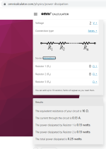
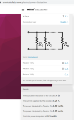
To get some particular SPL out of some particular loudspeaker there needs to be current x through voice coil which means voltage over the voice coil needs to be the same. Resistor in parallel with loudspeaker keeps the voltage on the loudspeaker terminals the same, but series resistor drops it. In other words, with series resistor current drops for given amplifier voltage because circuit impedance went up, so we have to use more amplifier voltage to get the current through voice coil back up.
A parallel resistor seems waste of amplifier power for no obvious benefits, while the series resistor wasting same amount of amplifier power could reduce acoustic distortion from the loudspeaker and noise from amplifier, perhaps alter frequency response of the loudspeaker, depending on the loudspeaker drivers and the crossover network within. This is because distortion and noise sources are voltage as well, and at same voltage per same acoustic SPL regardless of circuit impedance and amplifier output voltage in use. Now with series resistor circuit impedance goes up, current from these goes down so acoustic output from them goes down. With parallel resistor circuit impedance through voice coil stays the same and none of this happens.
Using good amplifier with low noise, good drivers with low distortion, and good system design it is possible to have good performance without wasted power.
This is all the same stuff explained over and over again, circuit impedance 🙂 analyze circuit impedance from the drivers perspective to take advantage on any of this, distortion reduction, electrical damping and power amp noise reduction previously unlisted 😉
yeah I should have written more specifically what the load was 🙂 if it was a driver connected to an (low output impedance) amplifier directly then yeah, adding series resistance would change acoustic frequency response of the system because the total impedance for the voltage would vary less with frequency than before, basic stuff and at the core of the whole backEMF thing.
Assuming it was some random complete loudspeaker with some kind of a crossover network within: If you would add resistor outside the loudspeaker like Joe suggests, then the "could" is appropriate word I think because there could be shunts in the crossover to compensate the impedance over frequency bandwidth, flattening impedance, like in the Elsinore. Its possible to have crossover network within the loudspeaker such that source impedance has no effect on the acoustic frequency response, voltage division with any external additional series impedance stays constant over the frequency bandwidth.
How about amplifier power? with series resistor current through voice coil goes down so we need to increase voltage to get same current through voice coil to maintain acoustic output. With parallel resistor the current through voice coil stays the same, but the parallel resistor draws additional current from the amplifier so amp power is up. Both cases, about same amplifier power is required to maintain acoustic output, both waste power as heat in the resistor. Simplified resistor / parallel calc attached to illustrate.


To get some particular SPL out of some particular loudspeaker there needs to be current x through voice coil which means voltage over the voice coil needs to be the same. Resistor in parallel with loudspeaker keeps the voltage on the loudspeaker terminals the same, but series resistor drops it. In other words, with series resistor current drops for given amplifier voltage because circuit impedance went up, so we have to use more amplifier voltage to get the current through voice coil back up.
A parallel resistor seems waste of amplifier power for no obvious benefits, while the series resistor wasting same amount of amplifier power could reduce acoustic distortion from the loudspeaker and noise from amplifier, perhaps alter frequency response of the loudspeaker, depending on the loudspeaker drivers and the crossover network within. This is because distortion and noise sources are voltage as well, and at same voltage per same acoustic SPL regardless of circuit impedance and amplifier output voltage in use. Now with series resistor circuit impedance goes up, current from these goes down so acoustic output from them goes down. With parallel resistor circuit impedance through voice coil stays the same and none of this happens.
Using good amplifier with low noise, good drivers with low distortion, and good system design it is possible to have good performance without wasted power.
This is all the same stuff explained over and over again, circuit impedance 🙂 analyze circuit impedance from the drivers perspective to take advantage on any of this, distortion reduction, electrical damping and power amp noise reduction previously unlisted 😉
Last edited:
Sorry I'm flooding it but its nothing new so feel free to skip.
Thought to post this last one, VituixCAD has View > power dissipation window, which can be utilized to see current through the driver or any other component. This can be toyed around to find out what changes with high amplifier output impedance, or any impedance network between the amp and driver.
It doesn't provide view on acoustic distortion of course, but one can put the voltage source in series with the driver to emulate what currents backEMF voltage would do in the system. Or imagine the voltage source is the mains hum and what happens to acoustic output with added series or parallel resistor. Or inspect current of the driver / any component to evaluate when the current is up or down.
the backEMF example. Current flows through amplifier output impedance, and about none goes through the parallel resistor. The amplifier is here as Thevenin equivalent on the left represented by the output impedance only. The voltage source is next to the driver emulating backEMF voltage source in the driver.
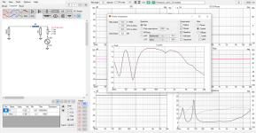
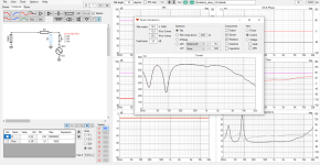
The added series resistor reduces current from the backEMF voltage, but the parallel resistor doesn't because output of the amplifier (on the left) shortcircuits it. Current through both the amplifier output and the driver is the same on both cases, they are atop each other on the dissipation window.
Here is currents, amplifier like usual, driver unmuted to see frequency response et all. Parallel resistor changes the amplifier load impedance, draws additional current. Current through driver stays the same with or without the resistor, so acoustic output is the same.
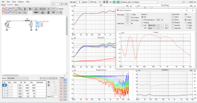
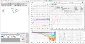
These few images visualize all the my posts on this subject in this thread 😀 If someone is wondering whta the heck, its easy to replicate, open kontiainen-demo project shipped with vituixcad and experiment away.
Thought to post this last one, VituixCAD has View > power dissipation window, which can be utilized to see current through the driver or any other component. This can be toyed around to find out what changes with high amplifier output impedance, or any impedance network between the amp and driver.
It doesn't provide view on acoustic distortion of course, but one can put the voltage source in series with the driver to emulate what currents backEMF voltage would do in the system. Or imagine the voltage source is the mains hum and what happens to acoustic output with added series or parallel resistor. Or inspect current of the driver / any component to evaluate when the current is up or down.
the backEMF example. Current flows through amplifier output impedance, and about none goes through the parallel resistor. The amplifier is here as Thevenin equivalent on the left represented by the output impedance only. The voltage source is next to the driver emulating backEMF voltage source in the driver.


The added series resistor reduces current from the backEMF voltage, but the parallel resistor doesn't because output of the amplifier (on the left) shortcircuits it. Current through both the amplifier output and the driver is the same on both cases, they are atop each other on the dissipation window.
Here is currents, amplifier like usual, driver unmuted to see frequency response et all. Parallel resistor changes the amplifier load impedance, draws additional current. Current through driver stays the same with or without the resistor, so acoustic output is the same.


These few images visualize all the my posts on this subject in this thread 😀 If someone is wondering whta the heck, its easy to replicate, open kontiainen-demo project shipped with vituixcad and experiment away.
Last edited:
There TNT, once again, falsely accusing me of rampant commercialism. That is not only unfair, it is a lie. I have been extraoridnarily generous because that is how I am by nature, and some are reading this (am I allowed to have silent fans?), and they know that it is not me that is lying.
To DT, keep going.
To the rest, haven't you got a box of resistors somewhere? Does that give you any ideas?
Cause and effect = if you have an effect , then you must have a cause.
To DT, keep going.
To the rest, haven't you got a box of resistors somewhere? Does that give you any ideas?
Cause and effect = if you have an effect , then you must have a cause.
NB^I don't think it is deliberate.
So no, not "rampant commercialism" - but some somewhat questionable "advertisement"... hence - the debate 😉
//
Hello All,
If you have the interest take a look at this test equipment/jig over at AP.com. See the visual of what using a analyzer and current sensing resistor looks like.
You will need to sign in to see the setup.
https://www.ap.com/download/imp1-users-guide-2/?wpdmdl=5841
Thanks DT
If you have the interest take a look at this test equipment/jig over at AP.com. See the visual of what using a analyzer and current sensing resistor looks like.
You will need to sign in to see the setup.
https://www.ap.com/download/imp1-users-guide-2/?wpdmdl=5841
Thanks DT
Hello All,
Yesterday I was back at the bench and tested a new Vishay wirewound NS02BR100F resistor.
I tested the Vifa P17WJ-00-08 driver and got exactly the same test plot as the current sensing resistor inside the APx1701.
The next test plot will be current distortion plots of the P17WJ-00-08 with a parallel 8R test resistor with its' own current sense resistor.
Thanks DT
Doing the same (leaving the room + unwatching), who needs the acrimony in search of an Elsinore update, sound review or building photograph. I for one don't need protection from evil electronic theories and commercial entanglements nor do I require educating in said subjects. It's too much, too abrasive, and quite frankly, boring. Good luck Joe, thanks for your contributions. I'll be "watching" from further afield.You can have that debate by yourself. Bye!
[JR has left the room.]
Hello DT,
Let the above not stop you from publishing your findings. I for one am curious to learn how the experiments will work out in terms of measurements.
Let the above not stop you from publishing your findings. I for one am curious to learn how the experiments will work out in terms of measurements.
Agreed, I was referring to the acrimonious, and tedious "debates" in the name of protecting the truth as if it has one owner. I am equally interested in measurements etc. That said, I don't see an end to the acrimony. Guess I should have pressed "unwatch" a few minutes earlier.
Good luck Joe, thanks for your contributions.,, I am equally interested in measurements etc.
Thanks. I know what you mean. And me too.
I have been listening to the March P262 stereo power amplifier. The best solid state amplifier I have heard. And I am sort of a tube guy. Will be meeting up with Alan March at the Sydney HiFi Show starting on Friday 28th. If anybody reading this is able to go, don't miss his room.
I have no affiliation, in case anybody suspects this is an ad.
www.marchaudio.com/product/p262-stereo-power-amplifier/?v=6cc98ba2045f

"You will find us in the Lavender Bay room on the ground floor. Please stop by and we can have a chat." 😊
I have no affiliation, in case anybody suspects this is an ad.
www.marchaudio.com/product/p262-stereo-power-amplifier/?v=6cc98ba2045f
- Home
- Loudspeakers
- Multi-Way
- The "Elsinore Project" Thread