Like these? 200 watt 8 ohm...bought years ago for setting bias in a couple old Adcom amplifiers.

Pretty fancy ones! But yes, anything to fully load the power supply on it's own before connecting amplifiers - basic test, easily done - same thing with a Variac for slow power 'ramp-up' and simple oscilloscope/computer interface to actually see the waveform on the amp/pre/etc

The new transformer arrived today, after detouring to Sacramento from New Jersey before making its way to Tx.
It’s alive. I relocated new rectifier blocks to either side of the filter board, then let the power supply cook for a while before powering the boards one at a time.
Offset was -50ma on both sides after an hour or so. It spikes to .25 volts briefly when switched off, but I don’t know if that’s normal.
Reassembling the case tomorrow to let it rest where it’ll live before setting final bias again.
Seems good?
First, thanks to @Mark Johnson and all of the folks who have helped make this design a reality
I've finally tried one channel of my M2X with an Ishikawa attached and no speaker load.
On the plus side, I was able to get the output offeset to <10mV.
However, the lovely salvaged, skived heatsinks (from a Carver 900 "The Receiver") don't appear up to the task.
Specs:
* 47V rail-to-rail
* Id appears to be 1.32A
* Thus the two IRFP(9)240's are emitting ~60W. Or I don't remember well enough from EE 101.
* Power transistor temperatures measured with the thermocouple that came with my "Neoteck" DMM. It registered ambient temperature as 20C
* Temperature at the top of the heat sink is 52C
* Temperature at the base of the Drain pins is about 190C
Is this too much to ask from these Vishay IRFP(9)240 transistors?
Kind regards,
Drew
dliscomb,
By 47V rail to rail, you mean +23.5V DC on the positive rail and -23.5V DC on the negative rail?
With +/- 23.5V DC rails and 1.32A bias, you should be getting around 62 watts of dissipation - so you are close enough with your calculation.
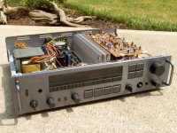
I found a pic on the Internet (shared below) of the Carver 900 Receiver with the top cover off and the heat-sinks visible.
Is that single heatsink or 2 heat-sinks placed face to face?
You have any pics of channel you have got up an running?
By 47V rail to rail, you mean +23.5V DC on the positive rail and -23.5V DC on the negative rail?
With +/- 23.5V DC rails and 1.32A bias, you should be getting around 62 watts of dissipation - so you are close enough with your calculation.
I found a pic on the Internet (shared below) of the Carver 900 Receiver with the top cover off and the heat-sinks visible.
Is that single heatsink or 2 heat-sinks placed face to face?
You have any pics of channel you have got up an running?
Attachments
@zman01 , thanks for the reply. I do mean ±23.5V.
yes, that is the heat sink in question.
The "spine" of the heat sink is 290mm x 80mm x 5mm.
The fins are ~21mm from spine to tip.
Sounds like I need to shell out for another set from HeatsinksUSA, similar to those I got for my MoFo.
Kind regards,
Drew
yes, that is the heat sink in question.
The "spine" of the heat sink is 290mm x 80mm x 5mm.
The fins are ~21mm from spine to tip.
Sounds like I need to shell out for another set from HeatsinksUSA, similar to those I got for my MoFo.
Kind regards,
Drew
uh... yes?190c on the drain pins??
I mean; I'll check again today, but that's what I wrote down yesterday.
Last edited:
Holy crap.
I was hoping that was a typo from 90c, which is already much too hot and not good. But 190c? (375F) Wow. Have never heard of one running that hot.
The heat isn’t getting out of the device. So you’ll need a fan in the interim, and bigger heatsinks in the long term. This is at least half again the heat of mofo, so depending on how hot your mofo gets, you’ll need to determine what additional size you need.
Out of curiosity, what are you using for thermal interface on the mosfets?
That board looks quite nice, btw. Good soldering.
You really need the lock washers on the daughterboard hardware. It will loosen without them. (Thermal cycles are strong)
The heatsink is teeny and the blue pads are not very good (obviously) at moving the heat. I’ll send you some keratherm, check PM.
You really need the lock washers on the daughterboard hardware. It will loosen without them. (Thermal cycles are strong)
The heatsink is teeny and the blue pads are not very good (obviously) at moving the heat. I’ll send you some keratherm, check PM.
Out of curiosity, what are you using for thermal interface on the mosfets?
NoName light blue thermal pads. 🙄. They seem to work well on my MoFo, but then it is not running at almost 50V.
I have some mica, also salvaged from the Carver, but awaiting the end of Holiday Season before I can get another Appropriation Request approval for "goop".
Kind regards,
Drew
Last edited:
Thanks very much; I enjoy the process so I don't try to rush.That board looks quite nice, btw. Good soldering.
You really need the lock washers on the daughterboard hardware. It will loosen without them. (Thermal cycles are strong)
The heatsink is teeny and the blue pads are not very good (obviously) at moving the heat. I’ll send you some keratherm, check PM.
Yes re: lock washers; this is only a testbed setup, not intended as the final product.
Luckily, it seems the pads do the job of "electrical insulation", but apparently not up to the M2X requirements for "thermal conduction".
Many thanks for the kind offer!
Kind regards,
Drew
Well even with better thermal pads that’s still a tiny heatsink, though with a fan will be reasonably good enough for testing.
Drew,
For passive cooling you will need a much bigger heat-sink - for their Pass clone amp builds, many diyAudio builders use a chassis with 300 mm x 4u heat-sinks that have an 8mm thick base and 40 mm fins.
With a heat-sink like the one you are using, you definitely need a fan to draw away the heat.
Personally I prefer 350 mm deep chassis; in that case you can have possibly have a less tall heat-sink (130-150mm).
Thanks for your input, @zman01 ; since these are salvaged, I have no idea what their dissipation capabilities are.
Nevertheless, it seems for this project I have two variables to solve before I move on to packaging this amplifier.
I hope it will be a worthy successor to my MoFo, and to my AKSA-Lender (so to speak).
Kind regards,
Drew
Nevertheless, it seems for this project I have two variables to solve before I move on to packaging this amplifier.
I hope it will be a worthy successor to my MoFo, and to my AKSA-Lender (so to speak).
Kind regards,
Drew
After installing Keratherm pads and running for 40 minutes, the Drain pins of each MOSFET register 114 (N) and 105 (P) degrees C.Well even with better thermal pads that’s still a tiny heatsink, though with a fan will be reasonably good enough for testing.
The top of the heat sink registers about 56 degrees C, 80mm above each MOSFET
Ambient temperature registers as 23 degrees C, and my body temp registered as 35 degrees C.
Kind regards,
Drew
Luckily, someone else on the Internet helped out with a heat sink calculator.
If the worst case is that it's 35°C (I don't have A/C) and the "Max. Junction Temperature" parameter below is allowed to get to 120°C (specified maximum is 150°C), then I'll need a sink for each MOSFET with thermal resistance 1.672°C/W.
Other resistance parameters taken from the Vishay specification sheet for the IRFP240.
Last edited:
Two notable things -
1) the old insulators were really miserable at getting the heat out of the transistor, and the Keratherm is notably better. I was not expecting THAT big a difference however. Wow.
2) Your heatsink is still undersized for the job and you need a fan. (Or bigger heatsink) Something like a computer fan running slow will make an enormous difference.
- Home
- Amplifiers
- Pass Labs
- The diyAudio First Watt M2x