@6L6 and @6sX7 thanks for your acknowledgement. Results:
Cooked the M2x for a good 2-3 hours this morning. Left offset hovers plus or minus zero. Right settles around - 24mV plus or minus. I had two multimeters connected to the binding posts on initial powering in a room in the low 50's F ambient. Interestingly both channels started off with negative offset, -24 and -50 mV per channel approximately then as the amp warms up the offset improves.
I searched the term 'offset' both on this thread and throughout the site, and conclude no need for Post #3 blasphemy but certainly open to opinions there. Currently R6 = 47k and RV1 = 5k
First listen, now. Dropped it right into the rig occupied by Aleph J. With the amp on and preamp muted, it's dead quiet so no noise issues. Perhaps brighter than the J, which is expected per their circuit designs. The M2x build was the least frenetic and most deliberate for me, so like the reinforcement of it working first go. Slow and steady = good.
Question for you: I have the speaker polarity reversed at the posts as I've been running ACA's and the Aleph J. Should the M2x follow suit this way.
Endnote - daughters are Ishikawas with Jfet devices from Punkydawgs, only deletion there are the trimmer pots. I do have Milpitas daughters built and cleaned awaiting installation later.
No inversion that I know of. I have not built it so I'm assuming it is similar to the F4 and F6

Started up the M2x yesterday, and it sounds fantastic, Have only tested with the TUCSON input stage, but found some 2 pcs j74 and 8 pcs kl170 in some old oppa that I am in the process of unpacking.
also missing MV5070c for MOUNTAIN VIEW


also missing MV5070c for MOUNTAIN VIEW
Since the M2x build complete been running Ishikawa's. Though I did build Milpitas daughter boards originally also. It's a lovely amp and compares favorably to my Aleph J.
Today, I installed one daughter board in the M2x on the left channel only in an effort to directly compare. Probably wise to wait awhile for burn in, but initially, Milpitas seems to present with a bit more detail. I think I recall reading a post from a veteran credible member that most of the goodness from the main circuit is fundamental to the autoformer, and it seems that is right.
Next adventure planned is 6-24 active crossover underway. Then can use both the J and M2x.
Wishing you all well.
I had so many Peter Daniel power supply boards this is the first time I've used something else. If anyone spots any glaring omissions or has pointers I'm all ears 🙂
The PS is making 26.7 volts both side, no load.
Starting with Ishikawa boards since I already had jfets. I dont have a distortion analyzer so am assuming "P3" is left all the way open for now.
The PS is making 26.7 volts both side, no load.
Starting with Ishikawa boards since I already had jfets. I dont have a distortion analyzer so am assuming "P3" is left all the way open for now.
^ 🙂
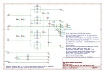
It seems like the PSU is perfectly functioning just based on your description. I'm not familiar with those boards. If you've got a schematic for them, that would be fantastic. I'm not understanding some of the labeling b/c it looks like it's labeled for mains input... and has placement for (perhaps) the NTCs that (perhaps) could be used for in-rush limiting and maybe a spot for a spark suppression cap... Looks like you've got an NTC in between mains earth and chassis GND for a ground lift...
On my screen, I can't zoom in enough to note the origin and do a search...
So, I admit that I'm doing a bit of
I'm more curious than anything... it's likely 100% fine. Can you post a schematic and/or more information about the boards?
The left and right channel amplifier boards appear . . . . not quite sure . . . . dusty? A quick going-over with a paintbrush or a shopVac or a few QTips dipped in isopropyl, might add to its evident beauty & glamour.
This little beauty (made in Italy!) gets the job done nicely, too.
This little beauty (made in Italy!) gets the job done nicely, too.
They are dusty! Cleaning them up with some isopropyl is a good idea, thank you 🙂
The PS board is a Randy Thatcher dual rail decoupled stereo power supply, attained by way of a certain gentleman and scholar famous for comprehensive build guides and general baddassery ( thank you again! ).
Edit: I was a little worried about proper grounding. Mains earth from the schurter switch is tied directly to the chassis. The PS board is tied to the chassis through an NTC using the same screw, from a point on the PS conveniently labelled "chassis ground." Is that right?
IIRC, I built all my last power supplies basically exactly to the original FW schematic so tried to more or less replicate that with these boards....except these are "decoupled." Not sure if/how that changes grounding. The two side of the PS are not currently tied together at any point....
Ahhhh.....this is what I did ( from the F4 build guide ):


Except the two sides of my M2X PS arent currently tied together as they are in the F4 build guide.
Except the two sides of my M2X PS arent currently tied together as they are in the F4 build guide.
^ Awesome. To me... you'd best consult with the man himself, but it looks like you can get rid of the terminal block and run the mains straight to the board with the cap and the thermistors currently on the block mounted to the board. The board then connects to your rectifiers / and the rectifiers back to the board for the filtering. The build guide might cover that. That's also a guess on my part. So...
re: the ground... (circuit ground) it has to be tied / connected in the "middle" (traces or a "ground plane"). Why b/c the "middle" of the bipolar supply is your ground. Maybe what you mean is that you don't have to put in jumpers to make that happen b/c the board already has the traces connecting it, and it can't be separated like the one from the store?
re: ground lift - Some of the boards by the same person have a provision for the thermistor for the ground lift on the board. So, it's best to really have the schematic.
Your safety ground seems fine best I can tell, but it's always best to have another set of eyes.
Last edited:
Looking at the PS Board information (ThatcherDIYAudio Stereo Class A Dual; Rail Decoupled Power Supply), the board has places for AC input capacitor and thermistors and DC ground lift capacitor. So all of those components may be placed on the board and the AC power may be connected directly to the board, the transformer primary may be connected directly to the board, and the PS ground may be connected directly to the ground lift thermistor on the board.
Edited: primary
Edited: primary
Attachments
Last edited:
Primary or secondary?the transformer secondary may be connected directly to the board,
Thanks for getting the schematic for them.
To me, it looks like the intention is to have mains in ... primary ... transformer secondary to off-board rectification ... DC output from rectifiers back to board for filtering?
Why would you connect the secondary to the board? Good chance for me to learn...
Thanks, Ben!
Perfect, thanks guys! I'll get that redundant block outta there, clean it up, and hopefully have it making music tonight 🙂
Just finished a pair of Troels Gravesen Bookshelf 3 way classics. They sound great with the F4, predictably - so I'm excited to hear them with the M2X.
Also, fwiw, the $50 antek trafo cover is a weighty lump of thick steel with a threaded plate on the inside that lifts the transformer up off the base plate. Totally worth it. Fingers crossed I wont need mu metal....we'll see!
- Home
- Amplifiers
- Pass Labs
- The diyAudio First Watt M2x