240 and 9240 are in correctly. How can I check what the the bias pot is set to (RV1)? When I try to test at R8 and VPOS it just moves up or down according to how I connect the multimeter. When I assembled the board I reduced R6 and put in 20k for RV1.
When you say the pot is set to high, do you mean that the resistance of R6 and RV1 is too great? Or too small?
When you say the pot is set to high, do you mean that the resistance of R6 and RV1 is too great? Or too small?
Last edited:
I think you mean offset pot, bias is set by the opto-unit 🙂That’s a big drop. Bias pot may be set way too high.
Also double check that you have the 240 and 9240 in the proper locations.
Henry, connect just one channel and measure the voltage across the power resistor in the psu, so you can determine the bias current. How is your DC offset? (shorted input, no load, just voltage at the output)

Hang on, sorry, I have F6 on my mind. M2x has only one pot, and it’s for offset. Bias is self-contained.
Yes, connect only one channel at a time for initial power up.
Yes, connect only one channel at a time for initial power up.
I am just ordering the correct resistors. Is it worth ordering and replacement parts for the M2X that may have been damaged? None of the parts look burnt.
I am just ordering the correct resistors. Is it worth ordering and replacement parts for the M2X that may have been damaged? None of the parts look burnt.
Don't worry, you did not burn anything. You just loaded your CRC Power supply down with those big resistors. As soon as M2x bias current slowly starts to flow, the big value of the Resistors starts to show as increased voltage drop on this resistors. You just shifted half of your total idle power dissipation to your CRC Resistors.
Only thing that could have been damaged are the CRC resistors itself.
And order a buncha dose 0R47. They’re cheap and you’ll use them again and again.
I started a brief discussion here about using the LH0033 for the M2X input stage, for which it is ideal on paper at least.
https://www.diyaudio.com/community/threads/diy-front-end-2022.394339/post-7235889
In order not to upset our moderator, I moved further discussion here.
Mark made a few remarks about it being expensive and difficult to get.
https://www.diyaudio.com/community/threads/diy-front-end-2022.394339/post-7236421
But you can still get them at ebay for reasonable price.
I bought 20 years ago, and can part with some if people in Europe might have interest to try.
And of course, the circuit is published, so I also have a discrete version, size and pin compatible.
https://www.diyaudio.com/community/...s-anyone-used-this-device.323828/post-5463168

🤓
Cheers,
Patrick
https://www.diyaudio.com/community/threads/diy-front-end-2022.394339/post-7235889
In order not to upset our moderator, I moved further discussion here.
Mark made a few remarks about it being expensive and difficult to get.
https://www.diyaudio.com/community/threads/diy-front-end-2022.394339/post-7236421
But you can still get them at ebay for reasonable price.
I bought 20 years ago, and can part with some if people in Europe might have interest to try.
And of course, the circuit is published, so I also have a discrete version, size and pin compatible.
https://www.diyaudio.com/community/...s-anyone-used-this-device.323828/post-5463168
🤓
Cheers,
Patrick
I'm not aware of anyone who built an M2x input stage daughter card using the LH0033. Certainly I never did.
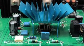
However I once did build a different, non M2x, amp project containing a pair of LH0033s, and displayed + demonstrated it at a Burning Amp Festival. In the attached photo you can see a socketed LH0033, with its heatsink on top, and "strap the mattress to the roof of the car" guy wires. Also visible are a couple nearby capacitors that were laid down flat, for vertical clearance to an LH0033 "emulator board" that I used during debugging and checkout. If there was a design error or assembly error in the initial boards, I preferred to destroy an emulator rather than an LH0033.
I really liked the looks of those anodized blue heatsinks with non-parallel dissipation fins. The guy wires, and pads of slightly-sticky phase change material from Laird, kept them in solid contact with the LH0033s. As member @pfarrell remarked at the time, yes I really did buy a spool of AWG-30 wirewrap wire with blue insulation, just for this purpose.
_
Attachments
I remember LH0033 has a much faster "bigger brother" in TO-3 housing?
6V/ns vs. "very slow" 1.5V/ns slew rate? .....something like that from memory.....
Could be a nice oscillator.......
I purchased some LH0033's from ebay when it was "advertised" in this forum. Could be fun to use them some day.......
6V/ns vs. "very slow" 1.5V/ns slew rate? .....something like that from memory.....
Could be a nice oscillator.......
I purchased some LH0033's from ebay when it was "advertised" in this forum. Could be fun to use them some day.......
yes I really did buy a spool of AWG-30 wirewrap wire with blue insulation, just for this purpose.
No-compromise DIY. 👍
Patrick
Love it.and "strap the mattress to the roof of the car" guy wires
I put in the R47 and everything is working fine with my test system. I will have to try it on my main system to see how it sounds.I found a parts error: I put 5 X 47R in the CRC filter when I should have put 0R47...
Ishikawa Input Board. Need Clarification.. I have searched and see both of the following being used.
In my search in the setting of the RV1 on the daughter board I seem to see two schools of thought.
1) Set RV1 so that the output is 0mV thus allowing to remove C1 or 2) set it so that the voltage drop across R1 and R2 is equal and let the output offset from the daughter be wherever it lies.
I have enough range on the RV1 to do either but not both.
If 2 is the answer then how much offset is acceptable before saturation of the Edcor becomes a concern and c1 becomes necessary.
I do have a REW/2i2 setup as well. What should I expect on the phase of the 2nd harmonic?
This is the THD of the amp with c1 shorted and offset to zero. 1 Watt = 2Vrms 4 ohm load. I will be trying some Mu-metal shield but not overly concerned as I really don't hear any hum. Amp is quiet.
If your amp is quiet with your speakers, give yourself a pat on the back.
My recommendation:
1. Remove RV1 from the Ishikawa boards; it’s not really worth the effort.
2. Build and listen to the Mountain View and Austin front ends. Compare w/ Ishikawa.
Enjoy!
My recommendation:
1. Remove RV1 from the Ishikawa boards; it’s not really worth the effort.
2. Build and listen to the Mountain View and Austin front ends. Compare w/ Ishikawa.
Enjoy!
Ishikawa has the advantage of being very flexible, as you note.
If you want to null the DC with RV1, that’s a great use of it. If you want to adjust your harmonic profile with RV1, by all means do.
I’m not a fan of DC on transformers and I am also not afraid of coupling caps, so having C1 in circuit is not a bad idea, imo.
You could also rig Ishikawa without RV1 nor C1, and you’d have the original front end as designed by Nelson.
Lots of choices.
- Home
- Amplifiers
- Pass Labs
- The diyAudio First Watt M2x