Working on the noise of the amp. Despite both of the amps being very quite. I set out on the quest to get them as quiet as possible. I switch the total config around with transformer up front, and everything power wise very tight and as far from edcor as possible. I then set out toplay with Shielding. Below is the impact of PFerrel's shield list in post 294. it is a single layer of 0.010" (muMetal).
I may squeeze another layer on once I get the other amp covered if I have enough metal. Quite an Impact!! In this test the input is grounded, and the output terminated into 4R.
First scope picture is with the exposed edcor. The yellow trace being V+ showing 15mV ripple @ 120Hz. The pink trace is the output. Seeing a kinda funky 1mVRms (7.36mVpp) output with 60Hz cycle. I am Really curious as to why the waveform appears this way.

The second frame capture is with the Edcor covered as explained above. Scope is untouched, channels and scale are the same. As you can see the output noise is still 60Hz, but the magnitude is now only 300uVrms (2.56Vpp)
.png")
Finally the third capture is comparing both channels. The Yellow Trace is Channel (1)
is the one seen above. The pink trace is now Channel (2). The Channel 2 is in identical condition as Channel 1 however, it is significantly quite with only 118.84uVrms (840uVpp) output. Similar wave form an60Hz.
I want to get Channel 1 as good as Channel 2 now.

I can make Channel 1 worse by getting in and touching components. I swapped IP Cards and it did not follow so it is in the main PC board. Channel 2 is not as affected by touch leading me to believe I have a poor solder joint or similar. It might even be caused by the slightly different layout I am very Interested in opinions and ideas on what to look for.
I may squeeze another layer on once I get the other amp covered if I have enough metal. Quite an Impact!! In this test the input is grounded, and the output terminated into 4R.
First scope picture is with the exposed edcor. The yellow trace being V+ showing 15mV ripple @ 120Hz. The pink trace is the output. Seeing a kinda funky 1mVRms (7.36mVpp) output with 60Hz cycle. I am Really curious as to why the waveform appears this way.
The second frame capture is with the Edcor covered as explained above. Scope is untouched, channels and scale are the same. As you can see the output noise is still 60Hz, but the magnitude is now only 300uVrms (2.56Vpp)
Finally the third capture is comparing both channels. The Yellow Trace is Channel (1)
is the one seen above. The pink trace is now Channel (2). The Channel 2 is in identical condition as Channel 1 however, it is significantly quite with only 118.84uVrms (840uVpp) output. Similar wave form an60Hz.
I want to get Channel 1 as good as Channel 2 now.
I can make Channel 1 worse by getting in and touching components. I swapped IP Cards and it did not follow so it is in the main PC board. Channel 2 is not as affected by touch leading me to believe I have a poor solder joint or similar. It might even be caused by the slightly different layout I am very Interested in opinions and ideas on what to look for.
I will make IPS6 boards.
Q1, 5 ZTX558 PNP bipolar xitor
Q2, 4 J113 Nchannel JFET
Q3, 7 KSC2690AY NPN bipolar xitor
Q6 KSA1220AY PNP bipolar xitor
Do only these jfet j113 need to be matched?
Other BJTs do not need to be matched?
How can I get matched j113?
Or ..
Which tools I need? I don't need a expensive tool. I am a newbie DIYer.
Where can I get KSA1220AYS? from ebay?
Last edited:
M2x is a project for intermediate- to advanced-skill builders. Except for posts #1 thru #4 in this thread, there's no handbook for assembly. There's no step-by-step tutorial with dozens of photographs. There's no training-wheels style instructional video. There's no Build Guide. The people who want and need those, shouldn't attempt an M2x.
The M2x input stage daughter cards which ship from the Store (Ishikawa, Mountain View, Tucson, Norwood, and Austin) are designed for intermediate-skill to advanced-skill builders. All subsequent daughter cards which are not in the Store, are definitely for advanced-skill builders only. Moffett Field, Black Forest, IPS6, IPS7, Cedarburg, et al, are only for advanced-skill builders. Any newbie builder who wants a pair of those cards, is advised to seek out a member with advanced skills, and beg them build the cards, for you. Find a mutually satisfying "barter" style compensation, such as sending them a nice bottle of champagne, or a big tin of local food delicacies, or anything that both parties can agree about enthusiastically.
Consider writing a post with a catchy title such as "Total newbie seeks M2x expert to assemble WXYZ cards. Will pay for your time!" or similar. Perhaps include the word mentor in your message.

Hello
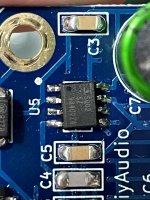
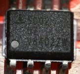
I couldn't find a close-up picture of a finished Norwood card showing the HA5002 operational amplifier.
Because of the very long delivery time of the op. amp. at the distributors I bought two from ebay (I know it was huge irresponsibility 😉). One is already soldered and the other (I think it is fake) is still "waiting".
What do you think they are all fake or am I lucky and the soldered one is original?
If someone could take a close up photo of a working Norwood panel I would appreciate it, it might be useful for others.
Thank you
Gyuri
i
Your top one soldered looks more like mine... ordered from known source. Can't speak to the bottom one...
Ignore the poor soldering, please. First SMD soldering I ever did on an actual project. Just goes to show that it doesn't have to be pretty to work. One of my favorite (if not my favorite) IPS.
Ignore the poor soldering, please. First SMD soldering I ever did on an actual project. Just goes to show that it doesn't have to be pretty to work. One of my favorite (if not my favorite) IPS.
Attachments
Thanks for the quick replies and the pictures.
My SMD soldering is much uglier, also a first attempt, plus I don't have a heat gun...
I haven't completely finished soldering the panel yet.
Anyone know of a reliable HA5002 source or have one of your own for sale? Farnell could deliver by October.

My SMD soldering is much uglier, also a first attempt, plus I don't have a heat gun...
I haven't completely finished soldering the panel yet.
Anyone know of a reliable HA5002 source or have one of your own for sale? Farnell could deliver by October.
I've powered it up with a bulb (60W) tester, no load and no shorting input.
There is no smoke or burning stuff on both channel amp boards.
I've seen this comment and bulb brightness time series graph. #3355 #6062
The bulb became brighter in about 30 sec.
Is this normal in bulb testing on this M2X?
Can I go ahead to the next step - disconnecting the bulb tester and inserting a shorting RCA input jack and powering it up and adjusting dc offset with RV1?
In bulb testing, the voltage drop to about 5VDC (I've connected a multimeter to power lines for another channel) when the bulb became brighter again.
And It seems the bulb became brighter fully.
I don't know it is normal.
And It seems the bulb became brighter fully.
I don't know it is normal.
I'm glad you found my post useful. What you're observing I would consider 'normal' for running both amplifier boards with a 60W dim bulb tester. If you have a >100W bulb and/or a <25W bulb you can try various combinations and see how the behavior and brightness / timing may differ. It might be fun to watch your DMM from the initial 'flip of the switch' through the bulb dimming and brightening. I'm making an assumption as to how your DMM is connected.
There are a number of wonderful posts around dim bulb testers, but I've always found the article in this link to be very helpful.
https://antiqueradio.org/dimbulb.htm
In Mark's post, you'll notice that he states the power consumption of a 'normally' operating M2x (with both channels operational similar to yours). If you cross reference that with the article linked... and notice how they describe the behavior of various bulbs... particularly for a bulb of roughly 1/2 the rated wattage of the 'radio'... I'd think you're good to go.
What I think your concern might be is the overall timing and the fact that the bulb went back to 'full brightness' vs. some level of dimness. Both the timing and final brightness would be affected by the overall power draw vs. the bulb's initial 'cold' and steady-state 'hot' impedance / resistance.
Mark's illustration could also show on the Y axis 'Power consumption'.
tl;dr - if your bulb had not dimmed at all, I would be concerned and recommend troubleshooting. I say remove the dim bulb tester and carry on with final DC offset settings and/or if you have a higher wattage bulb you can put it in as one last final hurrah to rest easier. However, I'd consider that more of a "fun" check vs. necessary. No need to go buy more bulbs.
I waited a bit for someone more knowledgable than I to post... No one has chimed in yet. So, I gave it a shot. I think I got it right. Hopefully someone will concur.
@ItsAllInMyHead
Thank you so much!
I disconnected the bulb tester and powered it up a channel.
I am on adjusting DC offset.
-8.5mv now
Thank you so much!
I disconnected the bulb tester and powered it up a channel.
I am on adjusting DC offset.
-8.5mv now
Adjusting dc offset of A channel seems OK.
It became 0.0mV automatically after one hour.
But B channel ended near (-)65mV after one hour.
DC offset of both channels started from minus values.
I felt that hooking up a speaker to A channel output gonna be OK.
It sounds indeed.
BTW, the dc offset has going down below -100mv and up over 100mV after powering the PSU down.
Is it safe on a connected speaker?
and... -65mV of B channel is safe?


.jpg")
It became 0.0mV automatically after one hour.
But B channel ended near (-)65mV after one hour.
DC offset of both channels started from minus values.
I felt that hooking up a speaker to A channel output gonna be OK.
It sounds indeed.
BTW, the dc offset has going down below -100mv and up over 100mV after powering the PSU down.
Is it safe on a connected speaker?
and... -65mV of B channel is safe?
I would be very concerned with the stability of your chassis design. It looks as if the only support holding the two heatsinks together is the M2X board?
Wow, those heatsinks are gorgeous!
Re DC offset, this is a common issue and can be solved by blasphemous heresy, described by @Mark Johnson but please don't tell anyone that I got it from him https://www.diyaudio.com/community/threads/the-diyaudio-first-watt-m2x.321925/post-7201332
Re DC offset, this is a common issue and can be solved by blasphemous heresy, described by @Mark Johnson but please don't tell anyone that I got it from him https://www.diyaudio.com/community/threads/the-diyaudio-first-watt-m2x.321925/post-7201332
@Plott
I've bought this heatsink with custom length cutting.
https://ko.aliexpress.com/item/1005003779418420.html
Thank you so much!
I will check the blasphemous heresy as you commented.
I've bought this heatsink with custom length cutting.
https://ko.aliexpress.com/item/1005003779418420.html
Thank you so much!
I will check the blasphemous heresy as you commented.
Yes. I thought it is not stable and am searching a proper method to connect the two heatsinks.I would be very concerned with the stability of your chassis design. It looks as if the only support holding the two heatsinks together is the M2X board?
I would suggest using a 6-10mm thick alum plate as a heat spreader that spans both heatsinks. Drill through holes(not tapped) and use M4 bolts/nuts to secure the plate to the heatsinks. Now you have one solid heatsink assembly. Drill and tap holes in the spreader plate to mount your M2X boards.
It's more work, but you'll have no worries afterwards 👍
It's more work, but you'll have no worries afterwards 👍
- Home
- Amplifiers
- Pass Labs
- The diyAudio First Watt M2x