I have some nice cannibalized power gear from an HPA-2 dual-mono. Two toroids and four of the large caps. It would be nice if I can use these in a dual-mono M2 but with the high 32v rating I'm wondering if there is a reasonable way to approach this or if it's just not worth the effort? Size wise they compare to toroids rated around 150W.

I tried finding that transformer online to determine the VA rating. There are a variety of "HPA-2" and "HPA2" products, so that does not help. However, if it's one of the many headphone amplifiers with that nomenclature.... the transformers are likely 'too small'. However, it's a possibility that they were vastly oversized for a typical headphone amplifier. If it's the one listed in the technical manual for a Rotel RA-1062, then you may be fine. I can't tell from the pic even with the cap for scale to make an estimate. tl;dr - if they're 200VA or 'bigger' you're likely fine for a dual mono M2(x). Either way, if you have more details then post them to be certain. Someone else may immediately recognize it and/or have better search skills / more time and be able to help.
You wrote M2, but you're in the M2x thread. Since you're here, I'd assume you may want to try some various input stages. There are written cautions re: excessive voltage for some of the input stages. I'd check that re: the ones you're considering.
Then I'd decide on the rail voltages you want.
Then, I'd maybe find a few PSU designs you like, then maybe ask in those threads how they might be configured using that transformer to get to the output DC you would like taking into account the expected load. I think there's a chance you could find a workable solution. It it worth the effort / cost? Your call after you determine what effort/cost might be involved.
The least effort (IMO), but not necessarily the least expensive, is the approach using monolithic rectifiers and a simple CRC filter like in the Pass schematics along with getting a single 2x18 Antek or similar 300VA transformer. Easy-peasy. As a side benefit, you'll also just 'know' it will work for a number of the First Watt amps if that's one of your goals. It's hard to stop at just one. 🙂
Hope you get to build it. It's such fun to swap out the input stages. 🙂
Welp, I lied. Turns out that toroid came out of a Rotel and there's just that one, which is likely too small for two channels. The ones I had in mind are from Madrigal for a very beefy Proceed HPA2 class AB. Now that I have the Madrigal Plitrons in hand It's obvious dual monos are way overkill. I found this- "Proceed HPA 2 has its own, dedicated power supply — including a separate 663 VA toroidal transformer for each channel." Yikes! Unfortunately these Plitrons have omitted the secondary V on the label and I can't find this specific part in the googles.I tried finding that transformer online to determine the VA rating. There are a variety of "HPA-2" and "HPA2" products, so that does not help. However, if it's one of the many headphone amplifiers with that nomenclature.... the transformers are likely 'too small'. However, it's a possibility that they were vastly oversized for a typical headphone amplifier. If it's the one listed in the technical manual for a Rotel RA-1062, then you may be fine. I can't tell from the pic even with the cap for scale to make an estimate. tl;dr - if they're 200VA or 'bigger' you're likely fine for a dual mono M2(x). Either way, if you have more details then post them to be certain. Someone else may immediately recognize it and/or have better search skills / more time and be able to help.
You wrote M2, but you're in the M2x thread. Since you're here, I'd assume you may want to try some various input stages. There are written cautions re: excessive voltage for some of the input stages. I'd check that re: the ones you're considering.
Then I'd decide on the rail voltages you want.
Then, I'd maybe find a few PSU designs you like, then maybe ask in those threads how they might be configured using that transformer to get to the output DC you would like taking into account the expected load. I think there's a chance you could find a workable solution. It it worth the effort / cost? Your call after you determine what effort/cost might be involved.
The least effort (IMO), but not necessarily the least expensive, is the approach using monolithic rectifiers and a simple CRC filter like in the Pass schematics along with getting a single 2x18 Antek or similar 300VA transformer. Easy-peasy. As a side benefit, you'll also just 'know' it will work for a number of the First Watt amps if that's one of your goals. It's hard to stop at just one. 🙂
Hope you get to build it. It's such fun to swap out the input stages. 🙂
To your questions about application, I am doing M2x builds. I have a few on the bench that run on a direct from DC power supply that the mighty Zen Mod designed to supply the negative rail. But I currently do not have a traditional mains fed power supply and I want something to bridge that gap. Budget constraints have me looking at parts on hand. Concerning the actual circuit I'm considering the First Watt power supply for the pure simplicity. I'll post the Plitron decal in the off chance someone happens to know what the secondary is. One final thought; I do have the silicon steel to potentially roll my own toroid and that would make for a pretty cool project. But honestly, if I can slap one of these Plitrons in the mix without needing extreme design changes that would be nice. Looks like my first step determining the mystery secondary- Edit: "F:50" What are the chances this means 50v? If that were to be the case, is it possible to configure the two channels in series for 25v per channel? So many mysteries lol--
Last edited:
Someone with more knowledge of that Rotel amp and/or in general how tightly / conservatively Rotels of that era were spec'ed might be able to tell you more re: the VA rating for the transformer. However, the tech manual for the amp lists 60W per channel (continuous output) and a power consumption of 300W. If the transformers were even mildly conservatively rated, then I'd assume... that it's at least 400VA. However, I haven't the foggiest, and my guess is just that .... a guess. So, if you can find a suitable PSU circuit to achieve the rail voltage you want, it might be fine for running two channels of an M2x. I'd wait for someone with more knowledge to chime in on that option.
re: the ones from the Proceed. Someone with more knowledge / time may be able to chime right in. Just looking at the rated power into 8 ohms for that amp (250W rms/channel), I'd assume that the output ACV of those transformers would likely be even higher than the one from the Rotel. Without knowing a bit more about the amp, I couldn't be sure, but it's a decent guess. Also, if they are 663VA, then they're likely physically pretty big. Plitrons are known around this forum for being very good, but I have no clue about their shielding. The M2x deserves a layout and power supply with good measures taken so that the transformer in the audio circuit doesn't pick up noise from the PSU transformer. tl;dr - Even one of those transformers is likely not the best fit for this application. If you feel safe, and you know how to use your DMM to identify the proper primary(s) and secondary(s), then you can hook it up and measure the output voltage. If not, let's hope somebody is just able to identify it properly and/or have a better guess than I from their knowledge of the HPA-2 and/or that transformer.
An alternative you may not have considered is a trade / sale. If you have no use for those Plitrons, and if you're not attached to them, my guess is that someone would very much like to have them. I'd also think that they're likely 'more valuable' than a transformer or a pair of transformers that might be more suitable for the PSU for an M2x. Just an odd idea if budget is a factor that deserves high consideration.
re: your question about 50V => 2x25. I wouldn't worry about that yet. Also, consider that you're talking about the AC voltage, not the DC voltage. DC voltage after rectification and filtering (even for 25VAC) using a typical PSU posted around here... is going to be ~30VDC and possibly higher. So, for now, I wouldn't worry about that option.
Again, I offer (at best educated) guesses. Wiser minds will likely be able to help you more.
Have fun and good luck!
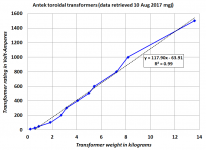
Bob Cordell's book points out that transformer manufacturers usually are very good at their jobs, and they build their transformers to achieve the desired specs at the lowest possible cost. This means: with the least possible copper in the windings, and with the least possible grain oriented silicon steel in the core. This means: transformer VA ought to be very well correlated to transformer weight.
A few years ago I grabbed some datapoints (weight, VA_rating) from Antek's website, and plotted the results. Cowabunga, Bob Cordell was right! See graph below.
If you're happy to assume that all transformers from all transformer manufacturers, are pretty darn close to Antek transformers ... ... ... then just weigh yours and find its approximate-VA-rating from the plot. The number won't be perfectly precise, but it will be an engineering estimate based on measured data. Not mere rectal extraction.
_
Attachments

About the ishikawa, do i get the same effect if i screw the pot to minimum as if i jumper it?
Ahh ty for posting schematic obvious after looking. So the easiest way is just to short all of them. Is there an advantage of using the pot over shorting it? And if so what is the easiest way to meaure it.
Perhaps that means the transformer is rated for 50Hz use?"F:50" What are the chances this means 50v?
No, don't do that either. Please no.Ahh ty for posting schematic obvious after looking. So the easiest way is just to short all of them.
Yes, a big advantage. The circuit needs the resistance to function properly.Is there an advantage of using the pot over shorting it?
Read up on voltage dividers and learn how to calculate a parallel resistance. Shorting all legs / pads together would effectively remove all the resistors from the circuit - R1 and R2 included.
Before you put in the pot, measure from wiper pin (center) to one outside leg. Measure from wiper pin to the other pin. Make sure they match (should be around 100R each for a 200R pot). The way many people do it (and it's close enough for me) is to just count 12.5 turns from the click in either direction (assuming a 25 turn pot).And if so what is the easiest way to meaure it.
I already soldered the pot. Can i measure where i marked on the pic or will it be wrong?Before you put in the pot, measure from wiper pin (center) to one outside leg. Measure from wiper pin to the other pin. Make sure they match (should be around 100R each for a 200R pot). The way many people do it (and it's close enough for me) is to just count 12.5 turns from the click in either direction (assuming a 25 turn pot).
That's exactly right; I found other units with a 50/60 rating, so good catch. After an hour of forensic part number deciphering of random Plitrons I have reached the conclusion that there is no way to glean the secondary voltage from the OEM versions. Unfortunately the input is more convoluted that I am comfortable with plugging into mains for a definitive answer and or a smoking hot enamel event. To Mark's handy lemma for sizing I can confirm these beasts are about double the size necessary to run both channels on a single toroid. There are enough cons at this point that I don't plan to pursue the Plitrons as a good option. Thanks to everyone for the suggestions!Perhaps that means the transformer is rated for 50Hz use?
I already soldered the pot. Can i measure where i marked on the pic or will it be wrong?
I recommend counting the turns.
Good news.. I finished assembling my M2x build. Bad news is that something seems off.
Maybe someone here can catch my mistake because I haven't found it yet.
The problem: I turned on the amp (after testing the power supply which is working as it should) with a multimeter connected to each speaker output, what I am seeing on both channels is in the range of 10v.
Adjusting RV1, I was able to drop this to 6v.
As far as I understand, this number should be 0v. This is the problem.
No smoke, no smell, no heat during the initial turn-on (second one after the bulb test)
Both channels are behaving/measuring the same so I'm guessing it a mistake I meticulously reproduced in both channels thinking I was following instructions.
Pictures attached.
Thank you.
Attachments
Is it possible that your R6 has only 37.4 ohms instead of 47kohms?Good news.. I finished assembling my M2x build. Bad news is that something seems off.
Maybe someone here can catch my mistake because I haven't found it yet.
The problem: I turned on the amp (after testing the power supply which is working as it should) with a multimeter connected to each speaker output, what I am seeing on both channels is in the range of 10v.
Adjusting RV1, I was able to drop this to 6v.
As far as I understand, this number should be 0v. This is the problem.
No smoke, no smell, no heat during the initial turn-on (second one after the bulb test)
Both channels are behaving/measuring the same so I'm guessing it a mistake I meticulously reproduced in both channels thinking I was following instructions.
Pictures attached.
Thank you.
Ooohhh…. Good eye! That would certainly explain the error thats showing up.
Yes, it’s a 37.4 ohm resistor because I intended to do the blasphemy heresy mod. I also changed the trim pot.
3. WARNING: BLASPHEMOUS HERESY! DO NOT READ THIS! Some DIY builders of the M2 amplifier, using the very fine “Tea‐Bag” circuit board, have reported a problem to the diyAudio forums. Their M2 amplifier’s output offset voltage is negative, and no setting of trimmer resistor RV1 removes this negative offset. I would like to gently mention a possible fix: leave R7=47K, but change R6 to 37K and change RV1 to 20K. Now (R6+RV1) can vary from 37K to 57K, in other words, from (10K less than R7) to (10K more than R7). This lets you null out either polarity of offset voltage. However, to faithfully reproduce Nelson Pass’s original M2 design, the M2X schematic and PCB silkscreen do not include this modification. M2X has R6=47K and RV1=5K. If you decide to make this R6,RV1 modification on your M2X, don’t tell anyone. And don’t quote me.
Please doublecheck the "blasphemous heresy" idea, one more time.
Get a kit like this, https://a.co/d/1wPrRFz It will be the same price or cheaper than 2 resistors + shipping from Mouser/DigiKey, and you’ll be able to make whatever resistor value you need.
A kit like this has saved the day for me more than once. 🙂

A kit like this has saved the day for me more than once. 🙂
Last edited:
- Home
- Amplifiers
- Pass Labs
- The diyAudio First Watt M2x