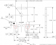
If you have plenty of extra male faston spade connectors, you can try some experiments on a few spare / expendable parts. Your idea to file them down just a little bit, might be worth exploring. See whether that gives a fit which pleases you more. Maybe "chamfer" or "round over" the 90 degree corners of the rectangular legs, and possibly also reduce or eliminate the triangular ears (red circles in attached image) . . . . whatever nips and tucks occur to you, and whatever it takes to make YOU happy with the fit.
I recall having the opposite problem when I built my M2x: the spade connectors were loose enough that I had to use blue painters tape to hold them in position for soldering. And then the tape's adhesive melted onto the spades during soldering, and I had to scrub it off with cotton swabs and isopropyl alcohol.
_
Attachments
Last edited:
To add to what bullittstang and Mark said, I would file them down so that they fit snugly into the hole, without too much force.
Mechanical stability comes from double-holed, two-sided solder support.
In fact, with my spades, I have to take care that the solder doesn't wick up too high on the connector, making connection with the mating part difficult. I usually wrap a few rounds of tissue paper around the upper part of the spade before soldering. That's enough to keep the solder from creeping up too far.
If solder has gotten too far, you can scrape / cut it off with a sharp knife - solder is soft enough, and much softer than the spade itself.
Regards, Claas
Greetings fellow audionauts,
The M2X is my third build, and the first to use 1/4" in. spade connectors.
The AMP brand connectors I received seem to have thick 'legs', and will not easily press-fit into the holes on the motherboard (GND.0, GND.P, VNEG, VPOS, OUTPUT). So far, the tips just barely reach the back of the PCB, and I fear trying to push them harder, lest the PCB be damaged. At the same time, I feel like part of the reason for using them is the mechanical advantage gained from having the connectors pressed tightly into the holes.
Is this expected? Am I missing some esoteric insertion tool? I could file down the legs, I guess. Looking at the photos of several builds, it seems to me that the connectors are fully seated down to the board.
I spent about an hour searching various forums (Parts and Construction) for combinations of 'spade connector', 'faston', and 'PCB', and 'board', but I didn't find anything close.
Kind regards,
Drew
The TE Conn part has thicker legs than some no name (much less expensive) brand ones. It’s ok to push it in for a press fit, I do that all the time. The 4 corners will cut into the PCB a bit but nothing major to damage the board. I do like the TE Conn spades the best though. They are the highest quality and thick for max current capability. I’m glad this amp has provisions for spades.
Faston spade connectors on PC board
@bullittstang, @chede
Thanks very much. This is very helpful.
@Mark Johnson, @xrk971
Thanks for the encouragement and for the ideas.
I have 100, so that's plenty for experimentation. A pair of needle-nose ViseGrips helps to get them down to the 'ears' without any other modification. I used a gentle rocking side-to-side to work it down into the holes.. I'll try slimming those 'ears' down and see if I can get it all the way down to the base.
Kind regards,
Drew
Attachments
Faston spade connectors on PC board
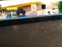
FWIW, filing down the 'ears' left the rest of the legs plenty big enough for a very snug fit into the holes.
Kind regards,
Drew
FWIW, filing down the 'ears' left the rest of the legs plenty big enough for a very snug fit into the holes.
Kind regards,
Drew
Please forgive me if this has been asked recently but too many pages to search.
Does anyone in Europe / UK have an up to date source for the MV5075C which seems to be unobtainium?
Does anyone in Europe / UK have an up to date source for the MV5075C which seems to be unobtainium?
The red LED is used as a voltage reference. It may be replaced by an LM4040, 2.048V, C grade. Change R3 and R4 to 182 and 90.9 Ohms respectively. That is how I have always run mine.
Post #3318 from August 2020 gives alternate possibilities. I just edited the top post in the thread to include this info.
Need A Ishikawa Board
Does someone have a spare Ishikawa board?
Not sure how I have only 1.
Or a set, whichever makes more sense.
I'd really appreciate it.
thanks,
Does someone have a spare Ishikawa board?
Not sure how I have only 1.
Or a set, whichever makes more sense.
I'd really appreciate it.
thanks,
Somethimg new for Xmas ?
A MOSFET shootout using the M2 output stage :
https://www.diyaudio.com/community/threads/complementary-power-mosfets.378024/page-2#post-6888301
Cheers,
Patrick
A MOSFET shootout using the M2 output stage :
https://www.diyaudio.com/community/threads/complementary-power-mosfets.378024/page-2#post-6888301
Cheers,
Patrick
I'm ready to order the M2X pcbs from diyaudio store, including also Toshiba matched jfets for ISHIKAWA board. Since there are two different options, 6-8 and 8-11ma, which is the best choice for this use ?
Last edited:

I ordered a pile of parts for the m2x a bit ago, while i checked part #'s and qty's i never checked details.
I'm sorting parts to start assembly and noticed that RV1 is the wrong pin out (staggered vs inline) even though the part number is correct.
Pictures of the product i can find show both inline and staggered (head scratch) and i can't find a definitive detail on any spec sheet on how to determine from part number which is which, other than visual inspection.
I suspect i just got the wrong part, but everyone is out, long back order times.
Over at newark i found 67WR5KLF which seems identical and in stock. Can anyone confirm as an acceptable sub?
power rating seems higher and voltage seems same.
I ordered a pile of parts for the m2x a bit ago, while i checked part #'s and qty's i never checked details.
I'm sorting parts to start assembly and noticed that RV1 is the wrong pin out (staggered vs inline) even though the part number is correct.
Pictures of the product i can find show both inline and staggered (head scratch)
Just (carefully) bend the middle pin to fit the board. You should find that it is plenty long enough and once fitted no one will ever know. 🙂
i was trying that, my biggest fear is turning the pot and the pins break.
i'll give it a go just to see if it will work until i can get the proper parts.
i think i see the issue.. the BOM lists W type part.
according to this https://www.farnell.com/datasheets/2710739.pdf the W type is not an inline pin package.
it might have been, but it isn't now. Looks like model Y is the inline and top adjusting part.
Did anyone else encounter this?
Yep, I had the same issue with RV1. I changed it out with a straight line version, but that was when they were available.
- Home
- Amplifiers
- Pass Labs
- The diyAudio First Watt M2x