1.5V in difference between positiv and negativ DC rail is a lot as the current draw from both rails should be equal.
Also the bias current through R13 and R14 is the same and as they have same value voltage drop should be about the same. But as they are 5% resistors if one is 5% on the high side and the other is 5% on the low side there will be a difference but more than 200 mV difference as you see is strange.
Is that with no speaker connected and DC-offset only a few mV?
There must be a "current leak" somewhere......
About the asymmetry.....if you have same AC out of both secondary......check just after bridge......just after the first set of capatitors.....just after the R in the CRC and so on to see where you see the difference showing up.
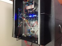
I think this is more a power supply than anything. Here are my measurements. I’m using the Universal Power Supply board with standard BOM, including TO-220 diodes, and an Antek 3218 xformer.. With no load, I get 12.33V on AC1A, 12.17V on AC2A, 11.79V on AC1B and 11.45V on AC2B. When I measure ahead of R1-4, i’m at +26.6V and then -26.5V at R5-8. I forgot to measure at + and - outputs to the amp boards. With both amp channels driven, it’s 11.24V on AC1A, 9.93V on AC1B, 10.92 on AC2A and 10.82 on AC2B. R1-4 are +24.83V and R5-8 are -23.99V. By the time I’m through the CRC I’m at +24.66 and -23.81 on the outputs to the amp boards. If anybody can look at those numbers and hazard a guess I’d appreciate it.
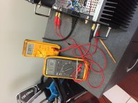
Are you trying to measure DC on the AC inputs? That will make things look weird.
The only place that matters is the output — put the meter to DCV, black probe on PSU ground.
Red probe to V+, it should measure somewhere around +24V.
Red probe to V-, should measure about -24V.
(Give or take a volt or two)
The only place that matters is the output — put the meter to DCV, black probe on PSU ground.
Red probe to V+, it should measure somewhere around +24V.
Red probe to V-, should measure about -24V.
(Give or take a volt or two)
Last edited:
No, I switched to AC for the secondaries and then DC after the diodes. I have a persistent voltage difference in my rails, and then beyond that a channel that has a big spread between R13 and R14, which I’m trying to figure out. When listening there’s a definite loudness difference between channels and a vagueness overall. My ultimate output is the voltage I mention as after the CRC filter, which is still close to a volt difference. I didn’t list them, but I get a lot of different voltage values on the pins of the diodes. I think I need to pull the PS board and check my soldering on the diodes.
To get symmetrical rails you need diodes that has about equal feedforward voltage drop. Nice to have same voltage drop over the two diodes that rectifies the positive sinus half and the two diodes that rectifies the negative half of the sinus. If you use diodes with very low feedforward voltage then a small difference in % will have less impact overall. If you can achieve this the transformer will be silent (if you also avoid DC at the transformer primary).
The problem with a large voltage drop difference over R13 and R14 sounds like another problem. First ensure that the two resistors are about equal and then measure with speakers disconnected.
The problem with a large voltage drop difference over R13 and R14 sounds like another problem. First ensure that the two resistors are about equal and then measure with speakers disconnected.
Start up went very well except for the not being able to get below 80mv. Off to the blasphemy mods.
Regards,
Dan 🙂
3. WARNING: BLASPHEMOUS HERESY! DO NOT READ THIS! Some DIY builders of the M2 amplifier, using the very fine “Tea‐Bag” circuit board, have reported a problem to the diyAudio forums. Their M2 amplifier’s output offset voltage is negative, and no setting of trimmer resistor RV1 removes this negative offset. I would like to gently mention a possible fix: leave R7=47K, but change R6 to 37K and change RV1 to 20K. Now (R6+RV1) can vary from 37K to 57K, in other words, from (10K less than R7) to (10K more than R7). This lets you null out either polarity of offset voltage. However, to faithfully reproduce Nelson Pass’s original M2 design, the M2X schematic and PCB silkscreen do not include this modification. M2X has R6=47K and RV1=5K.
Attachments

To get symmetrical rails you need diodes that has about equal feedforward voltage drop. Nice to have same voltage drop over the two diodes that rectifies the positive sinus half and the two diodes that rectifies the negative half of the sinus. If you use diodes with very low feedforward voltage then a small difference in % will have less impact overall. If you can achieve this the transformer will be silent (if you also avoid DC at the transformer primary).
The problem with a large voltage drop difference over R13 and R14 sounds like another problem. First ensure that the two resistors are about equal and then measure with speakers disconnected.
Thanks for the suggestions. I reflowed solder connections on the diodes and now am getting much more sensible readings. Measurements at R13 and R14 are all about 760mV. I’m still at about -65mV DC offset on one channel positive speaker output, but will let it cook overnight and see. The other channel is dead on.
Finally made this upgrade...systemic issues with loosening bolts over time...I do tend to board swap however. Also possible I didn't follow 6L6 washer formula to the letter 😀😀😀.
Worthwhile upgrade—I sleep better at night now.... in spite of the fact that I could make Cedarburg permanent and be totally happy.
Parts: male, female
Mouser also has this for $$—the pins on this version fit the daughter PCB holes better BUT they are also long—get a little close for comfort to the sinks—didn't try to cut them:
female
pfarrell,
Thank you for this tip. I am about to make my order. As I understand it, I would need (8) of the female [MIX-BUG HS] and as many as I need of the male [MIX-STG HS]. I currently have (40) of the male in my shopping cart given the number of daughter boards we have available. Shipping is ~ 27 euros 😱, is that right?
Thanks,
Anand.
OpAmp rolling ..
I feel like this Amp will keep me working forever.. After some listening of the IPS 6 card i decided to test some more OpAmps with IPS 7.
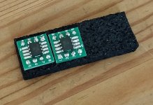
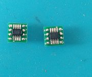
After the *CLICK* OpAmp blind test by AVdesignguru and Mark Johnson i wanted to compare the top 3 devices. So i ordered some SOIC-8 to DIP-8 pcbs and dropped an order at digikey and this week everything arrived. For me it was the first time soldering SMD parts. But with my new Hakko FX-888D and some flux it went fine.
I listened to the LM7321 and the OPA1612 now. In my setup and to my ears the LM7321 sounded a bit too "shouty" but had a nice presentation of details and bass. The OPA1612 sounded somewhat rounder and more pleasant to my ears, but the bass seems less strong compared to the LM7321 or IPS 6. Voices sounded strong and sweet but not shouty with the OPA1612.
I feel that I need *a possibility to switch between different input cards* like cubicincher build for his M2x. A really tempting next project...
I feel like this Amp will keep me working forever.. After some listening of the IPS 6 card i decided to test some more OpAmps with IPS 7.
After the *CLICK* OpAmp blind test by AVdesignguru and Mark Johnson i wanted to compare the top 3 devices. So i ordered some SOIC-8 to DIP-8 pcbs and dropped an order at digikey and this week everything arrived. For me it was the first time soldering SMD parts. But with my new Hakko FX-888D and some flux it went fine.
I listened to the LM7321 and the OPA1612 now. In my setup and to my ears the LM7321 sounded a bit too "shouty" but had a nice presentation of details and bass. The OPA1612 sounded somewhat rounder and more pleasant to my ears, but the bass seems less strong compared to the LM7321 or IPS 6. Voices sounded strong and sweet but not shouty with the OPA1612.
I feel that I need *a possibility to switch between different input cards* like cubicincher build for his M2x. A really tempting next project...
Attachments
pfarrell,
Thank you for this tip. I am about to make my order. As I understand it, I would need (8) of the female [MIX-BUG HS] and as many as I need of the male [MIX-STG HS]. I currently have (40) of the male in my shopping cart given the number of daughter boards we have available. Shipping is ~ 27 euros 😱, is that right?
Thanks,
Anand.
Yep, you are right about female and male. You could also consider buying more males if you have plans for the future buffer cards (I have now 2 of my empty cards already standing on these pretty legs and waiting for their components 😉)
Shipping and the price itself is quite expensive, true. This is an investment. But it's worth to do. To swap a cards you need about 5 sec. with them! 🙂
I ordered 8 female and 32 male.On the site it says that they are running low on the female ones.....Don´t know why,could it have sommething to do with M2x??😛
Did you manage to install the connectors to amp board without removing it from heatsinks?Yep, you are right about female and male. You could also consider buying more males if you have plans for the future buffer cards (I have now 2 of my empty cards already standing on these pretty legs and waiting for their components 😉)
Shipping and the price itself is quite expensive, true. This is an investment. But it's worth to do. To swap a cards you need about 5 sec. with them! 🙂
M2x is 3 years old; post #1 of this thread was made 2018 April 26th.
Maybe it's time for an enthusiastic and energetic Greedy Boye, to create brand new PCB layouts of all seven M2X PCB cards (AmpL, AmpR, Ishikawa, MountainView, Austin, Tucson, Norwood). But this time use board-to-board connectors which the readership of diyAudio overwhelmingly prefers instead of clunky M3 bolts and nuts.
Run a few "which M2y connector do you want?" polls on the site, with ever-decreasing numbers of possibilities, until you're down to just two final contenders. Then do a final shoot out and if there's an overwhelming winner: DO IT.
I myself am neither energetic or especially enthusiastic about this idea, so I won't be volunteering for the job. However it's clear to me that my opinion and I are part of a tiny minority, and several dozens of Greedy Boyz would literally jump at the chance to re-do the M2y using their fresh new ideas. Instead of the zinc plated M3 bolts and nuts favored by old fahts, 3 years ago. Release the Kraken! Launch big old hunkin' innovations! Wallow in the delightful pools of creativity juice the community will be jointly perspiring.
It'll be fun, they said.
_
Last edited:
Did you manage to install the connectors to amp board without removing it from heatsinks?
No, you definitelly have to remove the boards from the heatsinks to solder these D-subs. You have to be careful and patient while soldering them straight. Better make some jig to keep them straight while soldering. Then I was soldering male parts to the boards while they were inverted into the females which were already soldered on the main boards.
I am building a upstart delay and a dc protektion to my M2x.
Is it enough with 10A relays or should they be 16A?
Is it enough with 10A relays or should they be 16A?
The one I built includes a 16 amp relay, because I felt the extra amperes rating on the contacts, gave additional peace of mind and enhanced reliability. I didn't mind paying a little bit more money for peace of mind.
I used a relay whose Mouser part number was 655-RTD14005 from TE Connectivity / Schrack.
I used a relay whose Mouser part number was 655-RTD14005 from TE Connectivity / Schrack.
No, you definitelly have to remove the boards from the heatsinks to solder these D-subs. You have to be careful and patient while soldering them straight. Better make some jig to keep them straight while soldering. Then I was soldering male parts to the boards while they were inverted into the females which were already soldered on the main boards.
This!
My plan, once my connectors arrived, I will get one (+1) M2X daughter card
without components to make up a jig. After I removed the main amp board from the heat sinks, I will
1.) Solder males (x4) to the sacrificial board as close to 90 deg. with the aide of a protractor or carpenters ruler (if applicable).
2.) Attached the females to the males (x4).
3.) Test fit to the main amp board, already disconnected to the sinks, by inserting the other ends of the female sockets to the main amp board and checking if the pins are perpendicular to the amp board surface.
4.) Pre-solder (slight amount) the females to the main amp board from the top, OR use rubber bands to apply pressure to the two boards with the pins in-between, pins are flushed to the PCB's.
5.) Double checked with a pro-tractor and a ruler (in mm) making sure that 1/2 of the the triangle formed by the plane between 2 pins equals hypotenuse as square root of 2, adjacent is 1, and opposite is 1.
6.) Finally, apply solder to the females from the bottom of the main amp board side permanently .
Voila! Time to congratulate myself for a job well done.
The +1 card is for fitting and soldering females, using the already finish test jig (with males) as a guide for other boards needing males to avoid soldering inside the amp later on.... I think.
I kinda did it like this except the sacrificial board and parts. Made a small block of wood, marked and drilled 4 holes—drill press handy since they will come out 90 degrees, depth stop so they all match. Insert females into wood block—in my case the cap on the other side of board made a perfect support....
- Home
- Amplifiers
- Pass Labs
- The diyAudio First Watt M2x