Thanks Mark for an awesome project!
I've got all 5 input boards working and I'm
working on the other 2.
Lots of fun to be able to change inputs!
Bruce
I've got all 5 input boards working and I'm
working on the other 2.
Lots of fun to be able to change inputs!
Bruce
Attachments
Fire it up look for signs of problems, if none then check the GDS values again. Tweak RV1 as needed and if all holds well then you can go to the next step.
Last edited:
@ banderson Sweet! Nice job getting it going.
I know Nelson let's us put FirstWatt on designs, but I'm pretty sure adding his name is not permissible. I read where he put his name on them to differential between clones and his products.
You do have the MX designation, so maybe I'm wrong... I'm sure someone with more info will chime in.
JT
I know Nelson let's us put FirstWatt on designs, but I'm pretty sure adding his name is not permissible. I read where he put his name on them to differential between clones and his products.
You do have the MX designation, so maybe I'm wrong... I'm sure someone with more info will chime in.
JT
Interesting question about putting names on the clones. Actually, I was going to engrave "M2X by Nelson Pass", "F5 by Nelson Pass" etc. on my clones. No "First Watt" because I thought the company name could (should) be a registered trade mark. But I reckon "by Nelson Pass" just refers to the name of the creator of the circuit to honor him (and to show the value of the thing too). So, what are we indeed allowed to use on the front panel? Could anybody knowledgeable comment on that?
Bruce, congratulations on a nice looking build in #3961! Also congratulations on completing all five daughter card options. You'll have plenty of fun listening to them and discerning their individual quirks & personalities.
DIY Watts or similar but without company name, something nice looking,So, what are we indeed allowed to use on the front panel? Could anybody knowledgeable comment on that?
but not try being a copy/paste of the official Hi-Fi product= not the same aesthetic.
Just my feeling 😉 Write thanks 😀
The amplifier worked well for several hours, with no DB but with a shorted input. Stabilized offset, bias and temperature. 100hz noise disappeared but other frequencies dominate. I'm not worried about that yet. I will connect Ischikawa tomorrow. Thanks for the hints.
That noise is because the front end is floating... you have the input leads shorted, but there is no daughter, so the inputs shorted mean nothing with an open after it.... look at the schematic.
Don't get hung up on measurements right now, get it running check the offset and listen to some music. 🙂
Don't get hung up on measurements right now, get it running check the offset and listen to some music. 🙂
2sk1529/j200 - sufficient as output devices?
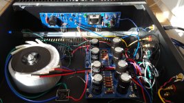
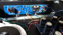
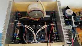
Santa Claus already paid a visit to my home and dropped of a Deluxe 4U 300 case, all black. It took me about 5 hours to assemble it. Now i will have to do all the wiring again because the wiring inside my prototype ist too short to plant it into the broad 4U enclosure. And i want to go star ground.
I got myself a soft start / temperature protection board from eBay (nobsound). Before i used one CL-60 on the primary of the power transformer. But i also got some CL-70 to try out.
I was looking for alternatives for the output stage MOSfets. Toshiba 2sk1530 / J201 are almost unobtainium. But i found some 2sk1529 / J200 - inside my old integrated amp Sony TA-F461 that will never connect to my speakers again. So i am asking you for your opinion:
Are 2sk1529/J200 a sufficient replacement for my IRF240/9240 devices? Will it be worth the effort to "slaughter" my Sony amp for the Toshiba output devices?
Attached: random image of my M2x test mash-up
Attachments
Ufff... Works fine. Connected Ishikawa cards. Voltage and bias correct. Temperature on mosfets 55 ° C. I have removed the connection between "gnd neg" and PS board. 100hz noise is not dominant. A bit quieter but I hear 250Hz and I don't know how to get rid of it.
Last edited:
Congratulations on the progress so far! 🙂
Do you have pics of the amp in its current state and a wiring diagram for how you've got it all connected? If so, please post. 55C on a standard biased M2x makes me think (relatively) smaller heatsinks=> maybe (relatively) smaller chassis=> maybe a bit cramped or wire routing is not optimal + maybe noise picked up at signal transformer.
Edited to add - You clearly said 55C on the MOSFETs, not on the heatsinks. DOH! Either way, pics / diagram may help.
Hi, Darrr. Everything seems to be fine from your description. Don't forget to set the output DC bias close to zero.
Concerning the hum, I could say this from my experience (I am a new guy also, so take it with what it is): I read somewhere that odd harmonics from power supply are mainly caused by the magnetic interference picked up by the circuit, mainly Edcors. I also had some hum in the beginning. Much less remained when I put a steel cover on the toroid power transformer and mu-metal shields on Edcors. I noticed that this helped mostly with the odd order harmonics (150, 250 Hz). I still have some 100 Hz hum remaining that I will try to work on some time, but it is hearable only with the ear next to the speaker, nothing at all at the normal listening position, so I am happy for now.
Concerning the hum, I could say this from my experience (I am a new guy also, so take it with what it is): I read somewhere that odd harmonics from power supply are mainly caused by the magnetic interference picked up by the circuit, mainly Edcors. I also had some hum in the beginning. Much less remained when I put a steel cover on the toroid power transformer and mu-metal shields on Edcors. I noticed that this helped mostly with the odd order harmonics (150, 250 Hz). I still have some 100 Hz hum remaining that I will try to work on some time, but it is hearable only with the ear next to the speaker, nothing at all at the normal listening position, so I am happy for now.


Lovely build and layout. I particularly like the rails coming from the sides of the CRC board.
I see a lot of things that look very well done, and I don't see anything that I can call out to try changing re: layout or wiring. Perhaps someone with eagle eyes may see something.
Alternatively, it's something in the circuit(s). Sadly, I am out of my depth there.
Good luck! 🙂
I see a lot of things that look very well done, and I don't see anything that I can call out to try changing re: layout or wiring. Perhaps someone with eagle eyes may see something.
Alternatively, it's something in the circuit(s). Sadly, I am out of my depth there.
Good luck! 🙂
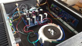
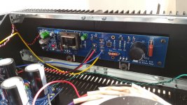
Here are the photos. The schematic shows a link that is no longer there: gnd.neg to PS.View attachment 899624View attachment 899625
Keep it simple and reduce the number of possibilities... First thing I would do is shut it down and pull the speaker input to the DC board and test from there and see if the 250Hz is still there and at the same level. If it's unchanged you have ruled out anything from the DC boards and can move on to the next thing.
Short the inputs and test, un-short and test changes?
I had a hard time finding where are kept my 220uf/10V green Nichicon for the IPS#6 boards.....then I had these in my mind as a "backup":
https://docs.rs-online.com/e583/0900766b80ebdd03.pdf
....has anybody tried them as audio coupling cap?
Now I will not experiment this time as I found the others.....but could be fun to know is anybody as tried them.
They (220uF/10V) has very low ESR (10 mOhm) and can handle very high ripple current (5.5A). They are made for DC/DC converter stuff.....
Got my "Thanksgiving Break" project finished finally, after a mis-wire burnt a resistor, I had to order some more. All done today:
1) Black Front Plates from ModuShop (no lettering this go-round)
2) Black momentary switches with blue LED (from a PC modding site)
3) Toroidy 300VA 2x20v transformers (Herbert is great to work with)
4) H9KPXG Switch/Soft Start Modules (designed by Mark Johnson)
5) SLB PSU board (by XRK971)
Still rocking the IPS7 with Sparkos OpAmp.
The new power supply measures right at 26v under load.
Sounding great! One day I will manage to post pictures here again.
Thanks to all involved.
Got my "Thanksgiving Break" project finished finally, after a mis-wire burnt a resistor, I had to order some more. All done today:
1) Black Front Plates from ModuShop (no lettering this go-round)
2) Black momentary switches with blue LED (from a PC modding site)
3) Toroidy 300VA 2x20v transformers (Herbert is great to work with)
4) H9KPXG Switch/Soft Start Modules (designed by Mark Johnson)
5) SLB PSU board (by XRK971)
Still rocking the IPS7 with Sparkos OpAmp.
The new power supply measures right at 26v under load.
Sounding great! One day I will manage to post pictures here again.
Thanks to all involved.
Have you tried the Staccato yet? I like it even better that Sparkos. 🙂
Both of those brands of opAmp fit the IPS7 boards without any modification?
Looks like it would be tight
Looks like it would be tight
- Home
- Amplifiers
- Pass Labs
- The diyAudio First Watt M2x