I have some of the self threading screws that does not "bite" anymore. First I thought that it was the holes in the rails that was "worn out" but I think it is some of the screws only. I considered trying next size of screws and cut larger holes but I think just new screws can do it......and I have got some.....
I have some of the self threading screws that does not "bite" anymore...
If you ever wear out the fixing hole, clinch nuts are a handy repair solution - with the added benefit of a machine thread.
https://www.mouser.co.uk/ProductDetail/PEM/CLS-M3-2?qs=l4Gc20tDgJIf4aXxvh3tSQ==
Interesting with these clinch nuts. Then I only have to look up in data sheet what hole size to drill so nut can be installed.
McMaster-Carr
I use these on my bottom panels, using long screws to hold the rubber feet securely as well.
I use these on my bottom panels, using long screws to hold the rubber feet securely as well.
Nice "finger" screws and clip-on nuts!
I will have the top off at least once more as I have started stuffing components in IPS#6 boards. I work a little every evening as a "relaxing" exercise.
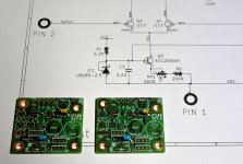
Impressing that the small blue cap is 2.2 uF......but it was only possible as a multilayer type.....
I will have the top off at least once more as I have started stuffing components in IPS#6 boards. I work a little every evening as a "relaxing" exercise.
Impressing that the small blue cap is 2.2 uF......but it was only possible as a multilayer type.....
Attachments
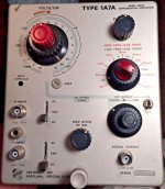
Hi🙂 It's me again... 😉 I would like to measure the noise with an oscilloscope again(on speaker the loudest is 250Hz) . I want to do it right but I don't know what settings to use, is the probe x10 or x1, V/div set to 10mV etc ... The autoset function sets me to 50mV and 500ns.(like on the pic)
Can someone smarter than me advise how to do it best?
Can someone smarter than me advise how to do it best?
You ned the scope to be set where it is most sensitive. You need 1x probe, AC coupling, and 1mV/Div or lower. The cheap digital scopes are not very sensitive and I don't think the right tools for this kind of noise measurement. These scopes often has too much "self noise" so what you see on scope is not the actual amp noise but a mix of "own noise, pickup noise and amp noise". If you can measure something that is from amp.....you can say that then the amp has a real problem.....e.g. if you measure a large signal at 10 mv/div. Is this the most sensitive setting?
Is it a bad thing that I have not screwed the tops on my monoblocks for the longest time? Seems like every time I do, I’m undoing it within a week.
Am I alone?
Definitely not alone, I love topless amplifiers 😀
Same part & same part-number were used on Mountain View daughter card and Austin daughter card. For almost the exact same purpose.Impressing that the small blue cap is 2.2 uF......but it was only possible as a multilayer type.....
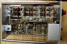
About noise measurement with scopes......look what they could do in the old days with scopes.....10uV/Div if this plug-in unit was installed and that was with tubes as input devices. I read the unit was later made with FETs. It must have been very clever designers back then. Think it was for the Tek type 555 scope.
Now with modern digital scopes.....you are lucky if you have 1 mV / Div sensitivity.....and it is "noise-free" at this setting?
Now with modern digital scopes.....you are lucky if you have 1 mV / Div sensitivity.....and it is "noise-free" at this setting?
Attachments
Same part & same part-number were used on Mountain View daughter card and Austin daughter card. For almost the exact same purpose.
OK!.....I also felt quite confident that I had got the right type of capacitor at RS-components.....that is my primary source for components.
Thanks Meper.
The lowest sensitivity is 2mV. I understand that only a good multimeter can measure something? Mine unfortunately only measures in the mV (AC range)
The lowest sensitivity is 2mV. I understand that only a good multimeter can measure something? Mine unfortunately only measures in the mV (AC range)
The best tools for DIY for these kind of measurement are (in my opinion) e.g. a 2i2 or alike sound card with e.g. REW software for distortion measurement (FFT). For prof. use other kind of equipment is available....e.g. expensive AP-equipment. Some vintage HP equipment etc. But it is "an art" in itself to be able to make these measurements correct so what you measure is actual the amp noise....and not something else. I have tried it....and is still improving.....
It remains to use my ears instead of the oscilloscope😉. I will try to borrow a better DMM and check the noise . After several hours of work, I checked the parameters.
L channel :
Q1 / Q2(in V)
S- 0.619/-0.612
D- 21.4/-21.4
G- 5.18/-4.87
Offset 3mV
R channel
Q1/Q2
S- 0.611/-0.620
D- 21. 4 /-21.4
G - 5.09/-4.9
Offset - 6.5 mV
Temp on mosfets 60°C, on heatsink 45°C
250Hz noise still on - 85dB. Smartphone at 3 cm from the speaker
L channel :
Q1 / Q2(in V)
S- 0.619/-0.612
D- 21.4/-21.4
G- 5.18/-4.87
Offset 3mV
R channel
Q1/Q2
S- 0.611/-0.620
D- 21. 4 /-21.4
G - 5.09/-4.9
Offset - 6.5 mV
Temp on mosfets 60°C, on heatsink 45°C
250Hz noise still on - 85dB. Smartphone at 3 cm from the speaker
Your ears are probably the best tool in the moment to "measure" if you have too much noise in the amp. And if it is 250 Hz you can hear.....something is bad in the PSU. I know from a thread in the Power Supply forum that asymmetry in PSU will cause uneven harmonics (some demonstrated it in Spice simulation tool). If your 2 x 18 VAC in reality is 17.9 VAC and 18.1 VAC this could cause these problems or the rectifier bridge does not have same voltage drop for positive and negative "half waves" of the sinus. If your rails are 100% identical (numeric)....like +23.8 VDC and -23.8 VDC...this indicates that you are ok with "symmetry". But if you have like +23.8 and -23.5....it is not "perfect" symmetry.
OK, so -+21.4 VDC are the rails as (D)rains of mosfet's are connected to rails. But if you go from 2 x 18 VAC which is about 25 VDC when rectified to DC....it is a large voltage drop from 25 V to 21.4 V. I remember that you have measured higher rails?
What is your total R in the CRC filter's? ....you have 7 parallel resistors?
What is your total R in the CRC filter's? ....you have 7 parallel resistors?
- Home
- Amplifiers
- Pass Labs
- The diyAudio First Watt M2x