I didn't connect any speaker yet. I will try it todayWithi no load, this does not matter.
Can you hear any noise on your speakers?
Ok. Here is the pic you wanted to see.Darrr- can you please attach probe and ground clip across a 100ohm resistor and post a photo ? Would like to see your background.
View attachment 897205
Attachments
Last edited:
Speaker is soundbar. 3R .
Channels individually measured. Additionally, reading from the phone application - a microphone in the closest distance to the speaker. I have to put my ear around 20cm to hear the noise.


Channels individually measured. Additionally, reading from the phone application - a microphone in the closest distance to the speaker. I have to put my ear around 20cm to hear the noise.
What is a soundbar 3R?
You probably need "real" speakers to be able to experience the "DNA" of a M2X amplifier.
You probably need "real" speakers to be able to experience the "DNA" of a M2X amplifier.
3R is impedance. The Sony soundbar is my work speaker. The working source is smartphone from headphone output.
And now I can say that the music is playing 🙂 The time for real speakers will come when I finish the back plate.

And now I can say that the music is playing 🙂 The time for real speakers will come when I finish the back plate.
Phew
Hi Mark,
that is a really tough job, particularly in through hole lay-out. Quite some time ago 😉 I might have designed something in McCad PCB and would immediately have been able to say whether or not it might fit in the (quite tight) sub-board space. These days, it's more complicated, though (can't use McCad on my mac anymore). I don't say no yet, but, have to look into possible solutions further (first impressions don't give too much hope though..).
On the other hand, conserving the zero-feedback characteristic of the M2 design seems very much worthwhile from my perspective, so in that regard a good diamond-buffer input stage appears quite a bit preferable over IC opamp inputs...
Either way, in case I figure out a way to cram all elements for the polished diamond into the chosen M2x footprint, I'll be back.
And if not.... either it ends here, or a further refinement of Nelson Pass's M2 may evolve 😎
best regards,
Mark
Hi @bambo/Mark, thanks for your message!
I think the M2x community would be delighted if you offered PCBs for those Austin-plus-improvements circuits! My experience is that 75% of M2x builders flatly refuse to attempt surface mount boards, so if you seek maximum "reach", stick with thru hole. How do I know this? Norwood.
Mechanical dimensions for M2x compatibility are presented in post #56 of this thread. It's a physically small board so you'll need to squeeze the PCB layout tightly. The existing Austin is already "kinda busy", see post #101
Thanks again and best regards,
Mark Johnson
Hi Mark,
that is a really tough job, particularly in through hole lay-out. Quite some time ago 😉 I might have designed something in McCad PCB and would immediately have been able to say whether or not it might fit in the (quite tight) sub-board space. These days, it's more complicated, though (can't use McCad on my mac anymore). I don't say no yet, but, have to look into possible solutions further (first impressions don't give too much hope though..).
On the other hand, conserving the zero-feedback characteristic of the M2 design seems very much worthwhile from my perspective, so in that regard a good diamond-buffer input stage appears quite a bit preferable over IC opamp inputs...
Either way, in case I figure out a way to cram all elements for the polished diamond into the chosen M2x footprint, I'll be back.
And if not.... either it ends here, or a further refinement of Nelson Pass's M2 may evolve 😎
best regards,
Mark
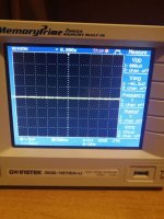
I decided to check the generated sine, triangle and square signals with an oscilloscope. Since I am a noob and I do not have many tools, my idea was to use a smartphone as the source of the generated signals. IMO sine and triangle look fine but the rectangle shows source oscillation. Can I read the last pic well - it's ~ 7MHz? This is without any signals on source
I would like some comments and ratings, please.


I would like some comments and ratings, please.
The squarewave is not oscillating or ringing, that is artifacts of the generated wave from the smartphone, which cannot make a genuine squarewave, but has to synthesize the increase in amplitude... and the amplifier is very accurately reproducing it.
I agree with 6, I looked at my amp values and they were consistent with yours. It's a great idea to listen and if something doesn't sound right, look for a problem. I think it remiss to do the reverse.
If you like it... don't look for a problem. 🙂
JT
If you like it... don't look for a problem. 🙂
JT
M2X no noise
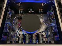
To use shielding, I chose to rearrange my F6 layout to accommodate the big steel shield over the transformer. Something needed to be vertical, so I moved the power supply and diode blocks (w/thermal paste) to the front panel. This did put the transformer in the center, closer to the Edcores but the shield seems to work. I'm hearing no noise or hum at all. Starting off with Tucson (604's, 1122's to sub in later) but I have parts for Ishikawa and Austin as well. I just wanted to share a photo and report that this configuration for me is very quiet.
To use shielding, I chose to rearrange my F6 layout to accommodate the big steel shield over the transformer. Something needed to be vertical, so I moved the power supply and diode blocks (w/thermal paste) to the front panel. This did put the transformer in the center, closer to the Edcores but the shield seems to work. I'm hearing no noise or hum at all. Starting off with Tucson (604's, 1122's to sub in later) but I have parts for Ishikawa and Austin as well. I just wanted to share a photo and report that this configuration for me is very quiet.
Attachments


Technical Equipment recco
I'm working my way thru the M2x board and have seen the above reference [originally from #4 post] to test equipment that can provide 25v DC to test the DB's. But I haven't seen any info on the kind of test equipment needed.
I'd appreciate info on what equipment I need to do that testing. I have several DMM's. What else do I need?
Thanks,
In early posts, 6L6 suggests testing the daughter boards before installing:
"If you decide to solder your Austin boards anyway, please make sure you’ve got adequate lab equipment to, at the very least, apply the requisite ±25V DC power supplies and measure the supply current. If you’ve got an incorrectly assembled board, it’s vastly preferable to have it catch fire on your lab bench, near your lab fire extinguisher, rather than inside your M2X amplifier."
I'm working my way thru the M2x board and have seen the above reference [originally from #4 post] to test equipment that can provide 25v DC to test the DB's. But I haven't seen any info on the kind of test equipment needed.
I'd appreciate info on what equipment I need to do that testing. I have several DMM's. What else do I need?
Thanks,
Last edited by a moderator:

Thanks. I was expecting something much more expensive.
Now I know what to ask for Xmas.
For completeness, here are broadly similar products, from the other three companies which are often considered peers of / competitors to , Siglent. As always, do your own research and make up your own mind. Before spending your own money.
GW Instek GPE-3323
Rigol DP832
BK Precision 1672
This is the noise measured at the loudspeaker. Measurement made by smartphone on temporary wiring and short circuited output. 
Here is what I attached to post #3377 ; click to remove the image distortion
Please feel free to decide what "matched" means, TO YOU, and assemble whatever test jig you like, in order to discover "matches". Just because I happen to be looking for pairs of J113s whose VGS's are identical when Idrain=3mA , doesn't mean you have to! In fact most of the JFET matching jigs I've seen here on diyAudio, aim at a different target. More than one different target in fact.
Hi Mark, i have build your jfet matching jig according to the circuit you posted in Post #3377. Now i am asking myself if I have done it right. I tried to check everything, i did make sure that every resistor ist in its correct position. I measured the voltage across the R4 2k2 resistor, it is 17,5V. I measured the current through R1 and i can dial it to 3mA WITHOUT "device under test" installed.
Without "device under test installed" i measured +1,345V at the TPs. With a jfet plugged into the circuit i get readings around -0,5 to -0,9V. Is this right? Is this wrong? I am confused..
Attachments

- Home
- Amplifiers
- Pass Labs
- The diyAudio First Watt M2x