Please have a look at the attached image, its file name is howdy_pardner.png
_
Thanks for that..
Polishing the diamond
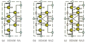
Mark here 😉 I saw your Austin buffer input, and it occurred to me that it can easily be bettered. Have a look at John Broskie's discussion of it. Or look up figure 25.7 in Bob Cordell's book. By cascoding the input BJTs by the output transistors, you can reduce the thermal load on the input transistors a lot, enabling higher quiescent current. Doing so, you can choose small input transistors with high hfe and match them so that the input base currents cancel each other. One ends up with the basic scheme Marantz used for their "High Definition Amplifier Module" (marketeerish for diamond buffer). I attach a picture of these, that I found on the net. Sure, a matched complementary jfet buffer as input is nice (see Erno Borbelly, Jean-Marc Plantefève or our Nelson Pass), particularly on one chip (alas Unobtanium), but ultimately it gets trumped by a polished diamond 😎. The higher parts count (and board space if you don't cram 😀) is easily justified by lower costs, hassle-free availability and above all superior performance.
greetings, Mark
Hi Mark,For those who hate, hate, hate Adobe Acrobat, here's the Austin schematic as an embedded image file. Click once to get rid of the obvious foreshortening distortion, and click again on the white "X" at bottom left, to see it full size.
~
Mark here 😉 I saw your Austin buffer input, and it occurred to me that it can easily be bettered. Have a look at John Broskie's discussion of it. Or look up figure 25.7 in Bob Cordell's book. By cascoding the input BJTs by the output transistors, you can reduce the thermal load on the input transistors a lot, enabling higher quiescent current. Doing so, you can choose small input transistors with high hfe and match them so that the input base currents cancel each other. One ends up with the basic scheme Marantz used for their "High Definition Amplifier Module" (marketeerish for diamond buffer). I attach a picture of these, that I found on the net. Sure, a matched complementary jfet buffer as input is nice (see Erno Borbelly, Jean-Marc Plantefève or our Nelson Pass), particularly on one chip (alas Unobtanium), but ultimately it gets trumped by a polished diamond 😎. The higher parts count (and board space if you don't cram 😀) is easily justified by lower costs, hassle-free availability and above all superior performance.
greetings, Mark
Attachments
Hi @bambo/Mark, thanks for your message!
I think the M2x community would be delighted if you offered PCBs for those Austin-plus-improvements circuits! My experience is that 75% of M2x builders flatly refuse to attempt surface mount boards, so if you seek maximum "reach", stick with thru hole. How do I know this? Norwood.
Mechanical dimensions for M2x compatibility are presented in post #56 of this thread. It's a physically small board so you'll need to squeeze the PCB layout tightly. The existing Austin is already "kinda busy", see post #101, and I think your new designs have even more components than Austin. However, aggressive and experienced builders claim that Austin is a "piece of cake", see post #102, so maybe I worry too much.
My own work on the M2x amplifier, after Austin, has been to create brand new IPS circuits unrelated to the predecessors. Two recent examples are "IPS6" and "IPS7" which are detailed in post #3408 of this thread. The next one after that, candidate-IPS8, is built and waiting its turn for testing. If it's good, I'll release it to diyAudio. Time will tell.
Thanks again and best regards,
Mark Johnson
Think I would be ok with SMD mount now after I tried it on 2018 line stage. I also got the very thin solder and solder tips....which helps a lot.
Maybe others are also "SMD solder educated" after building the 2018 line stage......who knows.....
Maybe others are also "SMD solder educated" after building the 2018 line stage......who knows.....
Oscilloscope connected at the output from the amplifier. Mountain View card, input shorted. What about this?I checked some of the points indicated and there are no significant differences.
DD-EE 45.8 / 46.6mV
EE-MM 1.034 / 1.035V
MM-KK 98 / 100mV
KK-JJ 44.8 / 45.4mV
Offset 0 / 6mV At the moment, I checked the bias and I have 0.61V on both channels through 0.47R resistors. I already know why there was such a difference - a mistake on r6. I did not check it after replacing the resistor. Thank you for your help.

Last edited:
If you have 10mVpp AC on output with shorted input......it is quite a lot noise. It is 100 Hz ripple if you have 10 mS / Div ?
What if you measure with DMM in AC mode? ....just to know if it is the scope/probe picking up some noise or it really originate from the amp output.
What if you measure with DMM in AC mode? ....just to know if it is the scope/probe picking up some noise or it really originate from the amp output.
Ok, so that is about 5-6 mV Vpp......if is was a sine.....so scope image looks right. For me that would be too much noise on output with my speaker sensitivity. I measure 0.0 mV at output on my M2X amps.
This is what the graph looks like with unconnected probes. Is it normal? How does this affect the measurements?
Yes, that is 50 Hz pickup from the environment. A scope has large input impedance. If you ground the probe it will disappear.
Hello guys,
Anyone willing to sell a pair of matched J113 for the IPS 6 (Q3,Q4) please PM me. I already have a pair so I only need another pair. I am in Diamond Bar CA 91765. Thank you and Happy Thanksgiving!
Abe
Anyone willing to sell a pair of matched J113 for the IPS 6 (Q3,Q4) please PM me. I already have a pair so I only need another pair. I am in Diamond Bar CA 91765. Thank you and Happy Thanksgiving!
Abe
I have about 1.1mV AC on both channels of my mono build.
DC offset 1.2mV on one and about 7mV on the other. I hadn't looked at those in a month or so. Next time they are fully warm I will go ahead and tweak the one the 7mV one down a bit.
This with daughter 7 and Staccato OPamps.
@amandarae shoot me a PM with your current pair specs and I'll see what I have.
Last edited:
How should I set time / div? As I set up 5us / div Vpp is ~ 3mV at the output of the amplifier At 10ms / div, the frequency changes very quickly between 20-200 Hz.If you have 10mVpp AC on output with shorted input......it is quite a lot noise. It is 100 Hz ripple if you have 10 mS / Div ?
What if you measure with DMM in AC mode? ....just to know if it is the scope/probe picking up some noise or it really originate from the amp output.
View attachment 897065
Darrr- can you please attach probe and ground clip across a 100ohm resistor and post a photo ? Would like to see your background.
How should I set time / div? As I set up 5us / div Vpp is ~ 3mV at the output of the amplifier At 10ms / div, the frequency changes very quickly between 20-200 Hz.
View attachment 897065
5-10 ms/div is fine for viewing 50 and 100 Hz noise.
It depends of how fast signals you want to view.
Best to look at the signal and do not look too much on the measurement figures the scope tries to make but the Vpp measurement figures seems OK.
Also maybe post an image here of M2X PCB with Edcor you showed at the other power supply thread. Then other people here can comment the copper tape you have around the core of the Edcor as I think it is not the best to do as it could cause core saturation in Edcor so signal will be attenuated when you connect amp to an AC signal source.

- Home
- Amplifiers
- Pass Labs
- The diyAudio First Watt M2x