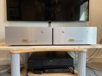
I did receive my Norwood boards, beautifully done by @pfarrell. So, I had the first experience changing the input boards. I was happy to have gotten the specific nut driver suggested in the OP, thanks for that suggestion Mark! No trouble changing the boards.
In the short listening session I had, vs the original Mountain View boards I had previously listened to, the Norwood was a bit more “precise”, as I felt the music was more “in focus”. On the downside, the music had a bit less “energy” than the Mountain View boards, which I think were more “dynamic” sounding. Sorry, I do suck at describing sound quality.
Extremely happy with either set ATM. Looking forward to trying the other 3 cards over time. I have ordered a double wide rack. I need to redo the front panels some day.
Attachments
Last edited:
Those are beautifully built! 😀
I'm sure many have asked prior, but are the plates with the amp name interchangeable? If so, brilliant. I swap amp boards in and out all the time, so it's been a challenge to decide what to do with any front panels. Hmmmmmmm. 😎
I'm sure many have asked prior, but are the plates with the amp name interchangeable? If so, brilliant. I swap amp boards in and out all the time, so it's been a challenge to decide what to do with any front panels. Hmmmmmmm. 😎
Nothing so special. I had the front plates engraved for an amp that never worked right, in fact, I stopped DIY over that. The Covid slack time, and the M2x project got me going again.
I was going to try the Ishikawa IPS next, but am wondering about my +/-26.5V rails. Even rails at 24V seem to stretch it assuming input voltages would go to 2 or 3 Volt, with the J74 having a V_GDS max of 25V. My rails are 10% higher, so I'm a bit worried.
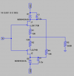
@TungstenAudio, you mentioned a while back you modified your Ishikawa IPS to deal with higher rails? I was looking for the post but could not find it, so I was wondering if one can just use a couple of Zener to bring the voltage down? Like in the schematic here. Or are Zeners too noisy?
@Zen Mod was mentioning Cascoding, is there a schematic for that somewhere?
Thanks!
Attachments
When i switch my M2x(Ishikawa) from stock ps to SLB, i was running +/- 29V'ish for weeks, no issues so far. Then i lower it to 27 just to be safer.
Think i read somewhere that jfets breakdown voltage is some where 35Vdc...
Think i read somewhere that jfets breakdown voltage is some where 35Vdc...
I'm also concerned there as mine right where yours are LATB. I've been running Ish now like that for maybe 80hrs, but do wonder long term...
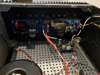
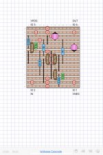
I tried a different way of "cascoding" the JFets in the Ishikawa IPS, which didn't work as well as I had hoped. In this instance, the simplest way is really the best. The circuit can have cascode devices added by inserting an NPN transistor above the Drain of the 2SK170, and a PNP device below the Drain of the 2SJ74. These devices operate in "common base" mode, as their Base terminals are held to a fixed voltage. The circuit may be implemented on a Vero board as shown below. I've used BC546 / BC556 transistors, but others will work as well, as long as the correct pinouts are observed.
The resistor values I've chosen will drop about 6.7 Volts from the VPOS and VNEG power supplies, and protect the P-channel JFet from excess voltage. (The N-channel is Ok for greater voltage.) I also added a 220uF, 63V capacitor between VPOS and VNEG to clean up the the supply in a manner similar to what has been done with the Mtn View IPS. I think this helps significantly, and may be responsible for some of the improved sonics that I hear with the other input stages.
The resistor values I've chosen will drop about 6.7 Volts from the VPOS and VNEG power supplies, and protect the P-channel JFet from excess voltage. (The N-channel is Ok for greater voltage.) I also added a 220uF, 63V capacitor between VPOS and VNEG to clean up the the supply in a manner similar to what has been done with the Mtn View IPS. I think this helps significantly, and may be responsible for some of the improved sonics that I hear with the other input stages.
Attachments
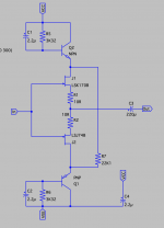
That is not quite correct. The 22.1k resistor needs to be connected between the bases of the two bipolar transistors.
I tried something different earlier, which didn't work well.
I tried something different earlier, which didn't work well.
Last edited:
great, thanks!!
Is there an "obvious" reason why the cascoding would be better than the Zeners?
I'm just learning (started getting into this only a few months ago), and maybe I should just try it -- but at $39 a pop for the LSK/J quad from the diyaudiostore, that's just a bit scary.
Is there an "obvious" reason why the cascoding would be better than the Zeners?
I'm just learning (started getting into this only a few months ago), and maybe I should just try it -- but at $39 a pop for the LSK/J quad from the diyaudiostore, that's just a bit scary.
The thing that I tried earlier was similar to what you suggested. Instead I used voltage references instead of the zeners. It didn't work, as in muffled sound from the amp after a minute or so. I tried analyzing the failure, but eventually moved on to other ideas.
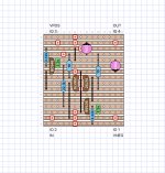
What we now have here is a simple cascode, where the bipolar transistors are operating in what is called "common base" mode. This keeps those devices at their most linear, and gives the cleanest way of lowering the supply voltage to the JFets while maintaining a low supply impedance. It also lets the JFets operate under constant Vds conditions, which improves their linearity.
What we now have here is a simple cascode, where the bipolar transistors are operating in what is called "common base" mode. This keeps those devices at their most linear, and gives the cleanest way of lowering the supply voltage to the JFets while maintaining a low supply impedance. It also lets the JFets operate under constant Vds conditions, which improves their linearity.
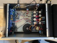
Bones13, Have you always been mono blocks or did you migrate up from dual mono. Differences? Are those 4u/300 boxes? What is the small board? What kind of pre are you using? Sorry for the litany of questions.
I have been trying to stuff everything into one box and I am asking myself why I am doing that.
Thanks, regards,
Don
I have been trying to stuff everything into one box and I am asking myself why I am doing that.
Thanks, regards,
Don
I have an Aleph J in a single 5u modushop chassis
The monoblocks were a more recent set, initially for another build. When I had more spare time with the Covid shutdown, I started back up again, and went with the M2x.
The small boards are speaker protection boards from XRK - available in the group buy forum, and on Etsy. Not at all sure they are required for the M2x. I have on and off thumps with the Aleph J.
Hmm, I made a mistake in copying the schematic from the Vero board design, but am confused about where the 22.1K resistor should connect:
does it go BC556-basis to BC546-emitter? shouldn't it go basis-basis?
does it go BC556-basis to BC546-emitter? shouldn't it go basis-basis?
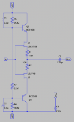
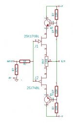
If you could devise a way for the bases of Q1 and Q2 to follow the output, then the drains of J1 and J2 would also follow the output. The sources of J1 and J1 already do follow the output; they're "source followers" after all. So if the drains follow the output and the sources follow the output, then: Vds is constant! No Vds modulation of distortion! Constant Vds means constant power dissipation, thus constant junction temperature. Additionally, Vgd is constant and Vgs is constant. These are the voltages across the input capacitances Cgs and Cgd. You've bootstrapped the gate capacitances and now they have no effect.
Whether or not this would actually sound better remains to be seen. It's a well known idea, which means Nelson Pass knew about it when he was designing the M2. But he chose to leave it out. Hmmm . . . ??
Whether or not this would actually sound better remains to be seen. It's a well known idea, which means Nelson Pass knew about it when he was designing the M2. But he chose to leave it out. Hmmm . . . ??
- Home
- Amplifiers
- Pass Labs
- The diyAudio First Watt M2x