I'm pretty fond of the Austin. So much so, that I adapted that design to use as the input stage to my F6. I needed something that would run at +/– 26V or higher. The Austin did the trick with a different pair of output devices (TTC004A, TTA004A).
The Mtn View is also worth experimenting with different JFets. There is a published design called Moffet Field which uses a set of J113 in parallel, and I have done my own flavor which I like to call Fremont, after the home town of Linear Systems. Both the plastic TO-92 and metal can versions of the 2N4416 are fun to listen to with customized current sources for the input and output transistors.
The Mtn View is also worth experimenting with different JFets. There is a published design called Moffet Field which uses a set of J113 in parallel, and I have done my own flavor which I like to call Fremont, after the home town of Linear Systems. Both the plastic TO-92 and metal can versions of the 2N4416 are fun to listen to with customized current sources for the input and output transistors.
"Where's the kaboom? There was supposed to be an earth-shattering kaboom!"
Driving me crazy, what movie is that line from? Google to rescue:
YouTube
Russellc
The Austin did the trick with a different pair of output devices (TTC004A, TTA004A).
Were you worried about the ZTX795A/ZTX696B? The data sheet didn't flag anything for me to run them at 26V rails (e.g. 140V for the breakdown voltages etc), but then, I also don't really know anything about electronics 🙂.
I was searching for your TTC004A/TTA004A, and I can find data sheets for TTA004 and for TTA004B,Q etc -- but googling for TTA004A (pr TTC004A) doesn't bring up anything really. Typo, or am I missing something?
BTW, I was running my new Austin IPS yesterday at +-26V, and it produced really beautiful sound and music, plus some heat from the output transistors...
That was a typo with the TTC / TTA parts, should have been TTC004B & TTA004B.
The ZTX parts are fine for the Austin application, but are somewhat challenged for longevity at the higher voltages. I was being cautious under advice from Mark J. I made a couple other changes as well, including Base stopper resistors for the outputs, instead of the RC network between the two bases. Sounds quite good.
The ZTX parts are fine for the Austin application, but are somewhat challenged for longevity at the higher voltages. I was being cautious under advice from Mark J. I made a couple other changes as well, including Base stopper resistors for the outputs, instead of the RC network between the two bases. Sounds quite good.
Attachments
Last edited:
Thanks -- if you're willing to share your design? I'm basically following your lead here 🙂 and am collecting ideas, also for your F6 build and experimentations.
You might be able to fit AAVID 5752 heatsinks onto the warmest transistors of an Austin board. I used them in the Noir design and they fit nicely even in a 1U-height chassis.
Calculate the transistor's expected power dissipation at the supply voltage you anticipate using, and then decide whether a 60 degrees C per Watt heatsink, would do any good.
Calculate the transistor's expected power dissipation at the supply voltage you anticipate using, and then decide whether a 60 degrees C per Watt heatsink, would do any good.
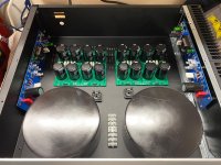
Does anyone know who built this M2x? I am interested in the regulated PS in particular.
https://i.redd.it/yv7hhng90f831.jpg
https://i.redd.it/yv7hhng90f831.jpg
Does anyone know who built this M2x? I am interested in the regulated PS in particular.
https://i.redd.it/yv7hhng90f831.jpg
That's an SLB supply...
The SLB (Smooth Like Butter) Active Rect/CRC/Cap Mx Class A Power Supply GB
Smooth Like Buttah SLB Class A PSU | Etsy
That the SLB (smooth like butter) power supply. It’s available from XRK, in the group buy forum, and Etsy. A lot of info on it in his thread in the group buy forum.
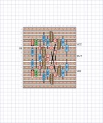
I don't know who built it but I do know the photo shows the single-ended Class A input stage daughter cards named "Mountain View". There aren't any Toshiba JFETs on that card, nary a one.
The SLB works well, and is what I used in my F6. If you go this route, I would recommend a 20V transformer (or two). I made the following substitutions to my SLB(s):
R1, R2: 18 Ohm
Q1 – Q8: IPP029N06N, (IPP040N06NAKSA1 and IPP034NE7N3 would also be good)
C7, C8, C13, C14: SLPX183M050H9P3 (18,000 uF, 50V)
Q9, Q11: KSC2690AYSTU, KSA1220AYS
Q10, Q12: MJW1302AG, MJW3281A
R17, R18: 1.8 Ohm
The end result was a lower dropout in the CapMx section. I also suggest adding from 10 mF to 24 mF to the output of the SLB to improve energy storage and bass response. This is foundational to the sound of the amp.
Last edited:
The SLB works well, and is what I used in my F6. If you go this route, I would recommend a 20V transformer (or two). I made the following substitutions to my SLB(s):
R1, R2: 18 Ohm
Q1 – Q8: IPP029N06N, (IPP040N06NAKSA1 and IPP034NE7N3 would also be good)
C7, C8, C13, C14: SLPX183M050H9P3 (18,000 uF, 50V)
Q9, Q11: KSC2690AYSTU, KSA1220AYS
Q10, Q12: MJW1302AG, MJW3281A
R17, R18: 1.8 Ohm
The end result was a lower dropout in the CapMx section. I also suggest adding from 10 mF to 24 mF to the output of the SLB to improve energy storage and bass response. This is foundational to the sound of the amp.
Sure wish you would have posted this about a week ago, I have two boards to original spec and I just built two more... it would have been nice to try your spec and do an AB. Ah well, maybe next time. We already spoke about the output caps. What else would you like to try without to much fussing?
Be careful making R17/18 so low. It may lead to oscillation. The value of 10R was chosen conservatively so that oscillation would be pretty much a non issue. The lower value will allow the cap Mx to track faster and lower the ripple at higher bandwidth. But may also oscillate. I had oscillations under certain conditions with even 2.7R there.
Also, making caps 18,000uF vs 15,000uF is not always best from standpoint of ripple current. It depends on what your operating steady state current is. The stock ones are designed for a 5A continuous load. If running lower current, a cap with lower ripple current spec could be used but best to run a simulation to see where everything is and if within the design space. Since the cap multiplier does such a good job, we don’t need as big of a bulk cap - which actually increases ripple current. Bigger is not always better in this case. Many people like low ESR caps and assume that’s always better. In this case you want caps that are not so low in ESR as they lead to higher ripple currents. (Not saying these 18mF caps are low ESR as they are same family SLPX, and quite similar).
Also, making caps 18,000uF vs 15,000uF is not always best from standpoint of ripple current. It depends on what your operating steady state current is. The stock ones are designed for a 5A continuous load. If running lower current, a cap with lower ripple current spec could be used but best to run a simulation to see where everything is and if within the design space. Since the cap multiplier does such a good job, we don’t need as big of a bulk cap - which actually increases ripple current. Bigger is not always better in this case. Many people like low ESR caps and assume that’s always better. In this case you want caps that are not so low in ESR as they lead to higher ripple currents. (Not saying these 18mF caps are low ESR as they are same family SLPX, and quite similar).
Last edited:
I am currently building M2x monoblocks out of some 400 mm 3U Pesante cases with 400mm by 300mm heat sinks on one side of each chassis. It didn't work perfectly so I had to re-drill some holes but I got one chassis put together.
The problem I am having is I have one AS-4218 but Antek is OOS. I am considering going with two AS-3220 transformers instead. Any problem with using these with 20V secondaries? I would imagine that gets me 25-26V rails.
The problem I am having is I have one AS-4218 but Antek is OOS. I am considering going with two AS-3220 transformers instead. Any problem with using these with 20V secondaries? I would imagine that gets me 25-26V rails.

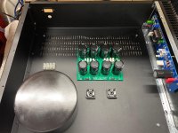
I ordered two AS-3220 for my build. My original goal was to build two monoblock M2x in separate chassis with the Edcor Transformer on the opposite corner of the Power Transformer in a cover, but I realized these larger chassis have much more space than expected. I wanted to get an opinion on how I should lay out the chassis. I chose to go the monoblock route because I was able to buy 2 Pesante 3u (with IEC hole), 2 pairs of mounting brackets, and the heatsinks for just under $300 and It allowed me to minimize transformer noise. The 5u deluxe chassis was $400 so I save a little over $100.
See below for the different options I have. The last picture just shows what the front looks like. I would like to swap out the 5mm to 10mm faceplates without the rack mounting holes so I can shift it over and it covers the heatsinks completely.
See below for the different options I have. The last picture just shows what the front looks like. I would like to swap out the 5mm to 10mm faceplates without the rack mounting holes so I can shift it over and it covers the heatsinks completely.
Attachments
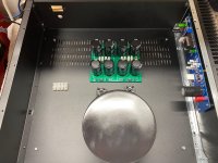
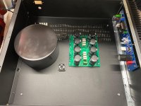
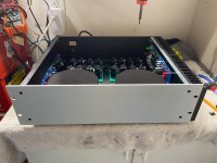
Yes, shielding and physical separation are needed to minimize the induced hum from the power transformers to the Edcor signal transformers. The last two pictures look like a good basic configuration.
The heatsinks will be plenty for an M2. Bias current is set automatically, and is independent of the supply voltage. That’s one of the neat tricks of the optocoupler circuit. Those block rectifiers will drop about 3.2V to 3.5V from the max of (20 x 1.4 = 28V). So expect 24.5V or a little more on the rails.
The heatsinks will be plenty for an M2. Bias current is set automatically, and is independent of the supply voltage. That’s one of the neat tricks of the optocoupler circuit. Those block rectifiers will drop about 3.2V to 3.5V from the max of (20 x 1.4 = 28V). So expect 24.5V or a little more on the rails.
- Home
- Amplifiers
- Pass Labs
- The diyAudio First Watt M2x