I have seen this done both ways. Removing the C1 and C2 caps seems to have merit. Depends on how clean the supply rails are, which is why I recommend the 220 uF cap between the rails. Sometimes C1 and C2 are taken to the opposite rail.
Just started my M2X mono build! I got the SLBs done and on to the amp boards. I will also be doing a soft start and speaker protect on this one... haven't done the speaker protect yet, so beware of newb questions! 🙂
A soft start is really not necessary for the M2x. The bias circuit has a very nice soft start mechanism built in. Just use a pair of NTC thermistors on the primary side of each power transformer, and you will be good to go.
I don't understand why DIY builders insist on adding speaker protection modules to the Nelson Pass designs. None of the FirstWatt amplifiers are sold with these. They are frequently responsible for problems with hum. Build the amp without the speaker protection, and go through a couple of offset setting and burn-in cycles of at least one hour to ensure that the final offset voltage is within acceptable range. (The M2 sets bias automatically.) After that, the industrial output Mosfets will be plenty reliable.
I don't understand why DIY builders insist on adding speaker protection modules to the Nelson Pass designs. None of the FirstWatt amplifiers are sold with these. They are frequently responsible for problems with hum. Build the amp without the speaker protection, and go through a couple of offset setting and burn-in cycles of at least one hour to ensure that the final offset voltage is within acceptable range. (The M2 sets bias automatically.) After that, the industrial output Mosfets will be plenty reliable.
No comment on to soft start or to not soft start—But I've been using nice push buttons for front power—keeping things family friendly—and this project has added some very nice safety and piece of mind (soft-start is a bonus)—plus M2X doesn't have an on board light show (except kinda Mountain View)—if that matters to you—It's also super fun to build:
PCB: low voltage On-Off switch drives AC mains relay \ includes soft start .. H9KPXG
PCB: low voltage On-Off switch drives AC mains relay \ includes soft start .. H9KPXG
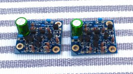
I was looking for a photo of an assembled Austin IPS board but could not find any...
Call me anal retentive, but I was wondering for the upright resistors which side the long lead should go, to the square pads, or the round ones, or maybe it's different for each and I should just look at the schematic to see where the "hot" vs the "not so hot" side is? I know, it's probably ridiculous...
But Mark must have had a reason to make one side of the pads square and the other round... what's the right way to do it? Thanks!
I was looking for a photo of an assembled Austin IPS board but could not find any...
Call me anal retentive, but I was wondering for the upright resistors which side the long lead should go, to the square pads, or the round ones, or maybe it's different for each and I should just look at the schematic to see where the "hot" vs the "not so hot" side is? I know, it's probably ridiculous...
But Mark must have had a reason to make one side of the pads square and the other round... what's the right way to do it? Thanks!
The square is the side where the shorter lead goes, you can see where he left room there for the larger diameter of the resistor... then the long lead goes to the round. (less room) This does make a difference for the layout as the carbon acts as an insulator... the design tries to keep two bare leads from being in close prox to one another. I/E you bend one a bit it hits carbon instead of shorting to another lead...
There's a nice hint there, look around the square pad and yo will see a circle, that circle indicates that something that size should go there... hence, above.
Last edited:
Member
Joined 2009
Paid Member
It matters not on resistors, knock yourself out.
I like to have all the resistors the 'same way up', so if they are 5% tolerance then I want all the gold stripes at the top 😱
I like to have all the resistors the 'same way up', so if they are 5% tolerance then I want all the gold stripes at the top 😱
I try and keep the orientation the same for troubleshooting, but I'm less anal about it than I once was... can't read those damned bans anyway, partial color blind. If two colors are close, noway I can tell.
There's a nice hint there, look around the square pad and yo will see a circle, that circle indicates that something that size should go there... hence, above.
Oh wow, I missed that one -- thanks!!
Oh wow, I missed that one -- thanks!!
No problem, these guys do a great job of helping us through their layouts. 😀
You can insert Austin's vertical-orientation resistors (member 6L6 calls them "soldiers") either way, and the board will work fine.
The schematic of Austin drives the PCB layout completely, since KiCad is an automatic-DRC, automatic-ERC system. Therefore, if you look real hard at the schematic and the layout, you can deduce the graphical convention for butted-lead versus bent-and-longer lead. What you see there is my attempt to make certain critical nodes available for easy electrical connection / probing, with a either a voltmeter or alligator clip or scope probe attachment clip. The bent-and-longer lead is much easier to access from the top side of the board.
The schematic of Austin drives the PCB layout completely, since KiCad is an automatic-DRC, automatic-ERC system. Therefore, if you look real hard at the schematic and the layout, you can deduce the graphical convention for butted-lead versus bent-and-longer lead. What you see there is my attempt to make certain critical nodes available for easy electrical connection / probing, with a either a voltmeter or alligator clip or scope probe attachment clip. The bent-and-longer lead is much easier to access from the top side of the board.
I was looking for a photo of an assembled Austin IPS board but could not find any...
Call me anal retentive, but I was wondering for the upright resistors which side the long lead should go, to the square pads, or the round ones, or maybe it's different for each and I should just look at the schematic to see where the "hot" vs the "not so hot" side is? I know, it's probably ridiculous...
But Mark must have had a reason to make one side of the pads square and the other round... what's the right way to do it? Thanks!
Look at post #101
I hope to build my Austin boards this weekend. No beach due to the tropical storm headed to the gulf coast.
I also just heard my Daedalus Muse Studio speakers may be completed next week, and head this way soon. An exciting June, as compared to the last 10 weeks.
I also just heard my Daedalus Muse Studio speakers may be completed next week, and head this way soon. An exciting June, as compared to the last 10 weeks.
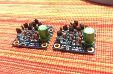
Finished the Austin boards, and listening now. These have the sweetness from the other 2 boards - the precision of Norwood and the energy of Mountain View at the same time.
I used the 0.4w vishay resistors that come in an 1/8th watt body. Tiny little things. I'm still traumatized by fitting all those transistors, with the data sheets printed out even.
My favorite of the 3 so far. Ishikawa and Tuscon built, but I won't listen to them this weekend most likely.
I used the 0.4w vishay resistors that come in an 1/8th watt body. Tiny little things. I'm still traumatized by fitting all those transistors, with the data sheets printed out even.
My favorite of the 3 so far. Ishikawa and Tuscon built, but I won't listen to them this weekend most likely.
Finished the Austin boards, and listening now. These have the sweetness from the other 2 boards - the precision of Norwood and the energy of Mountain View at the same time.
I used the 0.4w vishay resistors that come in an 1/8th watt body. Tiny little things. I'm still traumatized by fitting all those transistors, with the data sheets printed out even.
My favorite of the 3 so far. Ishikawa and Tuscon built, but I won't listen to them this weekend most likely.
"Where's the kaboom? There was supposed to be an earth-shattering kaboom!"
"Where's the kaboom? There was supposed to be an earth-shattering kaboom!"
😀
- Home
- Amplifiers
- Pass Labs
- The diyAudio First Watt M2x