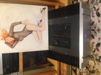
My first foray into Pappa's world. .......
when you confirm that Iq is 1A2-ish , with 24Vdc rails , you'll be in ballpark of 60-ish W of heat per channel ........ knowing these cases , I'll be content with some 40
so , Babysitter is way to go ....... or monoblocks
Monoblocks had crossed my mind. My rack has 4 ultra quiet fans (9dB) that run permanently to help with airflow and heat control. Proof will be in the pudding.. dB
My M2 ran all summer no prob in this lil' DIY chassis. It gets toasty, but not too toasty. I like my fets on the hot side anyway 🙂
The PSU is outboard. But, (and my record is skipping again) that's the best place for it.
edit: can't make the dam pic wrong side down
The PSU is outboard. But, (and my record is skipping again) that's the best place for it.
edit: can't make the dam pic wrong side down
Attachments
Last edited:
edit: can't make the dam pic wrong side down
If you're on Windows, you can download and use FastStone Image Viewer for free (for private use). To rotate a picture, press L for left (ACW) or R for right (CW) and save. I use it mainly to view pictures with, but it also has handy editing functions (like rotate).
For resizing pictures, I use the Paint program that comes with Windows.
Last edited:
If you're on Windows, you can download and use FastStone Image Viewer for free (for private use). To rotate a picture, press L for left (ACW) or R for right (CW) and save. I use it mainly to view pictures with, but it also has handy editing functions (like rotate).
For resizing pictures, I use the Paint program that comes with Windows.
... or you can do both of these tasks with IrfanView
IrfanView - Official Homepage - One of the Most Popular Viewers Worldwide
🙂
Best regards, Claas
... or you can do both of these tasks with IrfanView
True, IrfanView is excellent for editing pictures. I never liked it though, but I know of many people who use it.
FastStone is so much more than a picture editor. It's like Windows Explorer for pictures, and it can do editing as well.

There's more than one way to skin a cat, or to rotate a pic. Seems the forum had difficulty replacing the crooked one with the straight one I made, at that time.
My point was that I don't think that HK chassis is too far off - probably worth a try unless you're in the Mojave.
I love the use of the old HK cases!! I hope you can keep the meters operative. 🙂
If the heatsinks are a little small, it's amazing what dissipation benefit a small (or better, a larger but slow) fan can bring.
If the heatsinks are a little small, it's amazing what dissipation benefit a small (or better, a larger but slow) fan can bring.
I love the use of the old HK cases!! I hope you can keep the meters operative. 🙂
I should be able to, first to make sure the amp works, then futz with the anesthetic.
Those little fans I have are incredible. They are a necessary evil for their "keeping of the peace" function.
.. dB
It is actually a surprisingly sophisticated design task, to build a variable speed fan where the fan speed is proportional to (heatsink temperature rise above XXX degrees),
AND you demand that the minimum fan speed is less than 50% of the maximum fan speed, for super quiet operation when ain't much fan needed.
Why is this difficult? Because DC fans soil their diaper when you give them "inadequate" low voltage, and as a rule they won't start spinning from a dead state (Vfan=0) unless you send them enough voltage to spin at about 50% of max speed.
Running in that forbidden zone between 0% fan maxspeed and 40-50% fan maxspeed, requires electronic mastery (if not electronic wizardry), I assert without proof. Try it yourself and find all of the pitfalls, yourself. It ain't as easy as it appears to be. Which means it's a FUN design project!
How about a small arduino o raspberry pi and a PWM fan?
It will require coding, and some may frown upon the option to muddy the power supply cleanness, but... is it a path worth looking into?
It will require coding, and some may frown upon the option to muddy the power supply cleanness, but... is it a path worth looking into?
How about a small arduino o raspberry pi and a PWM fan?
It will require coding, and some may frown upon the option to muddy the power supply cleanness, but... is it a path worth looking into?
PWM works really well (no arduino needed) and one can get a PWM fan controller with adjustable setpoints for fan speedup and temp thresholds for about $5. The PWM driver board has a built in thermistor for temp sensing. It even has an audible buzzer to warn of fan stall/stoppage. With a 120mm fan on slowest speed setting I have to be within 12in to even hear it. Even so, with a heat pipe CPU cooler, it can extract 100w of heat from a MOSFET biased at 3amps and the MOSFET body temp rise is only 15C. I have also used with 80mm fans and smaller no heat pipe coolers (just small fins) and that cools well too.
This is the way the Alpha BB amp is designed to be cooled and working very successfully. You need a CLC filter in between the 12v wall wart and the PWM drive board to prevent noise from back propagating to your mains and getting into the amp’s linear supply.
Last edited:

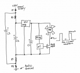
Sure, give it a try! If worried about high current & high frequency square waves contaminating the supply or contaminating the ground, you could use brute force as shown below.
There's no requirement that the fan circuitry must be directly connected to ground (or to the power supply), so we've decided to install R1-R4 and C1-C2 to make a super duper filter that sits between the noisy fan circuit with its AWFUL current waveform, and the delicate audio grade power supply.
Put it in SPICE, replace the microcontroller with a SPICE square wave voltage source, 20% duty cycle @ 100 kHz. Replace the fan by a 36 ohm resistor (giving a 333 mA fan current when on). Now see how small or how big your filter capacitors C1, C2, C3 need to be. Plot the current in R4 -- your goal is to make the waveform of this current, as clean as possible. Because that's the icky crud your circuit squirts onto the revered and honored Audio Ground. Maybe you only need small little capacitors (220uF??) to get a very clean current in R4 (?) Try it and find out!
Notice that you can't make R1-R4 arbitrarily large or else the fan will receive less than 12V when running at maximum speed. If we assume the 12V voltage regulator IC requires 15V input, then
After a wee bit of algebra,
edit added 10 minutes later- Hey why not connect this whole mess between +23V and -23V, so it never touches ground at all? Now you get to make R1-R4 quite a lot higher and get quite a lot more filtering from each microfarad of C1 and C2. But of course C1 and C2 now need a 50V rating
_
There's no requirement that the fan circuitry must be directly connected to ground (or to the power supply), so we've decided to install R1-R4 and C1-C2 to make a super duper filter that sits between the noisy fan circuit with its AWFUL current waveform, and the delicate audio grade power supply.
Put it in SPICE, replace the microcontroller with a SPICE square wave voltage source, 20% duty cycle @ 100 kHz. Replace the fan by a 36 ohm resistor (giving a 333 mA fan current when on). Now see how small or how big your filter capacitors C1, C2, C3 need to be. Plot the current in R4 -- your goal is to make the waveform of this current, as clean as possible. Because that's the icky crud your circuit squirts onto the revered and honored Audio Ground. Maybe you only need small little capacitors (220uF??) to get a very clean current in R4 (?) Try it and find out!
Notice that you can't make R1-R4 arbitrarily large or else the fan will receive less than 12V when running at maximum speed. If we assume the 12V voltage regulator IC requires 15V input, then
Vsupply >= 15V + (Fan_Max_Current)*(R1+R2+R3+R4)
After a wee bit of algebra,
R1+R2+R3+R4 <= (Vsupply - 15V) / (Fan_Max_Current)
edit added 10 minutes later- Hey why not connect this whole mess between +23V and -23V, so it never touches ground at all? Now you get to make R1-R4 quite a lot higher and get quite a lot more filtering from each microfarad of C1 and C2. But of course C1 and C2 now need a 50V rating
_
Attachments
Last edited:
How about a small arduino o raspberry pi and a PWM fan?
It will require coding, and some may frown upon the option to muddy the power supply cleanness, but... is it a path worth looking into?
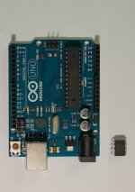
The PWM drive board that X posted is way cool. But if someone wants to go the microcontroller route, development can first be done on the Arduino. And then, provided the sketch is small enough, it can be ported to an ATtiny85, saving space, complexity and money.
Below is a size comparison of the Arduino Uno and ATtiny.
Edit: If the uC in Mark's sketch above means microcontroller, then the ATtiny should fit right in.
Attachments
Last edited:
Sure, use any digital electronics you like, whether it be a chip or a PCBoard or a little product in its own box. Arduino? sure! Raspberry Pi? sure! Teensy3? sure! MSPlaunchpad? sure! PocketBeagle? sure! Parallax? sure!
I'm just illustrating one way to ~harmlessly connect a PWM fan with powerful 100kHz noise spikes, to a "sensitive" analog supply in a class A power amp. In summary: Brute Force! Big caps, big resistors, lots of filtering.
I'm just illustrating one way to ~harmlessly connect a PWM fan with powerful 100kHz noise spikes, to a "sensitive" analog supply in a class A power amp. In summary: Brute Force! Big caps, big resistors, lots of filtering.
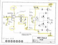
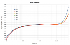
Here are some results of frequency response measurements of 6 Edcor PC600_15K in the M2X as shown in highlighted areas of the schematic. Frequency scans were 10 Hz – 50 kHz at 200 mV pk-pk. Measurements were repeated over several days as a reproducibility check. There might be some systematic error from the Digilent Analog Discovery 2 that I’m ignoring for now.
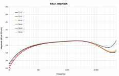
T1-1 is run 1 of transformer 1 without R5/C1, T1-1Z is run 1 of transformer 1 with R5/C1 in circuit...and so on. The 660pF and 10K are a measured values. I have more data but anxious to get the M2X built and test as a completed circuit. Both the Zobel and R6 and R7 (+RV1) affect the freq response so I'll show some variations on those values as Mark suggested.
Comments and suggestions welcomed.
Phil
Attachments
Fantastic job, Phil! Thanks so much for posting your data.
I myself would probably not reject any of those six transformers. Unit T1 differs by a tenth of a dB, which I doubt is significant. All of them are acting as (good) transformers and not as opens or shorts.
The before-Zobel and after-Zobel curves are truly fascinating. The Zobel that Nelson chose, seems to slide the HF "knee" over to the right, from about 12 kHz to about 32 kHz. While at the same time, very slightly rolling off the response between 1k and 12k (only -0.3 dB).
I notice that Bill Whitlock / Jensen Transformers refer to this RC circuit as a Damping Network (LINK) and they seem to judge its goodness by looking at the time domain waveform (Fig 21 ; also end of section 2.1.1) and comparing its square wave response versus a textbook Bessel filter's square wave response. Maybe Nelson did some of that too.
Very well done, hats off, bravo!
Thanks Mark. On the scales I used, T1 does look nasty but plenty useable as you said. The circuit is still within Nelson's specs for the M2: +0,-0.5 dB @ 20, 25kHz. It looks a lot prettier on a different scale.... R6, R7 and RV1 also help to flatten response. I'll post some more data in a few days.
And thank you for the link and suggestions. The problem reminds me of the C-RC in your Quasimodo work but here it's R-RC. I'm trying to learn AC analysis better and in the Quasimodo thread you posted "Here is the math to calculate power dissipated in the snubber resistor. It is typical of a homework problem given to 2nd year EE undergraduates taking their first Circuit Analysis class." along with calculations in a pdf. Are there some textbooks you would recommend?
Thanks again.
Phil
Attachments
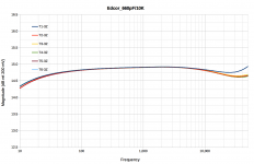
In production, transformers existed that were worse than that, so I
curved all of them and rejected the worst of them, about 15%
curved all of them and rejected the worst of them, about 15%

- Home
- Amplifiers
- Pass Labs
- The diyAudio First Watt M2x