This supplemental study guide is awfully good: link and chapter 12 of that book is on AC circuits. However you're going to need a working knowledge of complex numbers to analyze AC circuits; they are covered in chapters 10 and 11. The symbol "j" in AC analysis, means you're dealing with complex numbers which have a real part and an imaginary part. "j" is a complex number whose real part is zero and whose imaginary part is (+1 * j). "4" is a complex number whose real part is four and whose imaginary part is (0 * j). You're gonna love it.
Sure, give it a try! If worried about high current & high frequency square waves contaminating the supply or contaminating the ground, you could use brute force as shown below.
There's no requirement that the fan circuitry must be directly connected to ground (or to the power supply), so we've decided to install R1-R4 and C1-C2 to make a super duper filter that sits between the noisy fan circuit with its AWFUL current waveform, and the delicate audio grade power supply.
Put it in SPICE, replace the microcontroller with a SPICE square wave voltage source, 20% duty cycle @ 100 kHz. Replace the fan by a 36 ohm resistor (giving a 333 mA fan current when on). Now see how small or how big your filter capacitors C1, C2, C3 need to be. Plot the current in R4 -- your goal is to make the waveform of this current, as clean as possible. Because that's the icky crud your circuit squirts onto the revered and honored Audio Ground. Maybe you only need small little capacitors (220uF??) to get a very clean current in R4 (?) Try it and find out!
Notice that you can't make R1-R4 arbitrarily large or else the fan will receive less than 12V when running at maximum speed. If we assume the 12V voltage regulator IC requires 15V input, then
Vsupply >= 15V + (Fan_Max_Current)*(R1+R2+R3+R4)
After a wee bit of algebra,
R1+R2+R3+R4 <= (Vsupply - 15V) / (Fan_Max_Current)
edit added 10 minutes later- Hey why not connect this whole mess between +23V and -23V, so it never touches ground at all? Now you get to make R1-R4 quite a lot higher and get quite a lot more filtering from each microfarad of C1 and C2. But of course C1 and C2 now need a 50V rating
_
Thanks, Mark. Great stuff here and nice useful info.
For what it's worth... I used a CLC filter (green little PCB in photo above - no calculations - just stuff I had lying around in my bench drawers) and luckily it worked well. 1000uF // 1mH // 1000uF with 51R bypass resistor on 1mH. 100nF film bypass caps on 1000uF. This is a standard JPs64 power supply filter board he includes on all of his preamp circuits. Vunce did the same thing and saw his noise go away too.
Using a separate 12v Class 2 Wall wart to power the PWM via the CLC seems to work pretty well.
Tucson board polar capacitor for C1?
Hello, and thanks for these amazing boards.
I already have some Nichicon 220uF polar capacitors that I would like to use for C1.
Would the square on the board still represent positive? Would seem consistent with the other marking, but somehow seems backwards. I know non polar is recommended, but is there a problem with polar (other than not knowing which way to install it)?
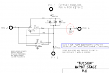
The last time somebody asked this question, 6L6 suggested that if the UES greensleeve capacitors were not an option, these bipolar capacitors from Panasonic (Mouser link) would be a suitable replacement. The Tucson daughterboard uses bipolar electrolytic capacitors because the offset voltage could be either positive or negative; there's no way to predict. Fortunately, bipolar caps don't care, they work equally well either way.
I recommend reading pages 5 and 6 from the Electrolytic Capacitor Application guide published by Cornell Dubilier link to pdf, especially the part about reverse bias voltage leading to the production of hydrogen gas. That's what you really, really want to avoid.
I've attached a .csv formatted "spreadsheet" from Digikey, showing the 220uF bipolar electrolytic capacitors they have in stock. Maybe one or more of them is available from your favorite distributor, whether that be DigiKey or Mouser or Arrow or Newark or whoever.
_
Attachments
Hello, and thanks for these amazing boards.
I already have some Nichicon 220uF polar capacitors that I would like to use for C1.
Would the square on the board still represent positive? Would seem consistent with the other marking, but somehow seems backwards. I know non polar is recommended, but is there a problem with polar (other than not knowing which way to install it)?
In my search for M2x parts I found that Mouser had everything I needed except for the 220uf cap and led’s needed for a few of the daughter boards. Digi-Key seemed to be well stocked in both so I ordered a few pairs of each from them.
In my search for M2x parts I found that Mouser had everything I needed except for the 220uf cap and led’s needed for a few of the daughter boards. Digi-Key seemed to be well stocked in both so I ordered a few pairs of each from them.
The 220uf UES greensleeve caps were out of stock when I ordered my Tucson and Mountain View components from Mouser. However, the 330uf were in stock, so they now populate both boards.
The 220uf UES greensleeve caps were out of stock when I ordered my Tucson and Mountain View components from Mouser. However, the 330uf were in stock, so they now populate both boards.
Which points out the tremendous advantage of waiting until you have the PCBs in your hands, before ordering parts. How much room do you really have, to use a larger diameter capacitor if you want to / need to ?? Not in theory, in reality. Answer: measure the dadgum board itself. Maybe you would even be willing to purchase smaller versions of nearby components, to make room for Big Mama. You won't know, you can't know, until you've got the boards in your hands.
This is doubly true for rabid dog aficionados of Russian / Obsolete Japanese / American Military-Spec film capacitors, who hope to fit a two inch long axial component where an 0.75 inch long radial component appears on the PCB. To you I say: measure, ruminate, contemplate, and bodge cleverly. Or bodge ham-fistedly. Your call.
I picked up the 16V version for the Tucson
UES1C221MPM Nichicon | Mouser
They have 400 odd in stock.
My amp powered up and is sounding great. Heatsinks sit at 52degC without a fan and the fet is at 63degC.
My rails are at +- 18.5
So a baby but still sounds very powerful on my test rig
Thanks to Mark and 6L6 and of course Nelson for the opportunity to build this very cool amp.
.. dB
...The Tucson daughterboard uses bipolar electrolytic capacitors because the offset voltage could be either positive or negative; there's no way to predict...
There are two capacitors in the signal path already, adding a third won't make a lot of differance; ac couple the MX2 input, add an asymetric potential divider across the Tuscon psu, tap off the centre with 1M and connect to the input of the OPA604.
You now have a guaranteed offset and can use a polerised cap instead.
Or you could use the old trick, two polar caps connectec in series (-++- or +--+), connect the centre to the apropriate supply rail via a high value resistor; the caviat is Ct=1/(1/C1+1/C2)
Last edited:
Why not just use bipolar caps. Only difference is that both alu foil layers has the thick layer of oxidation. This is a better solution than connecting two polar in series.
I think you missed the point, some people are eager to hear their new creation, rather than wait for parts to become available again, there is usually a solution to 'get you up and running' even if it's not ideal.
OK 🙂 ….I missed that one 🙂 …..ordering components at e.g. RS.....it usually only takes one or two days. He must be very eager. I don't like to de-solder components at PCBs…..if it can be avoided…...it looks nicer that way.
Hmm, 3 new resistors and 1 new capacitor, bodged onto a little 35 x 40mm PCB? Much scraping off soldermask and non-thru-hole soldering will occur. (times two amp channels). The end result might require new, longer bolts which affix daughterboard to motherboard. You may need to increase the daughter's spacing above the mother board, allowing extra height for new bodge components on the bottom side of the daughterboard. Be certain to buy some additional threaded spacers on your next parts order. (a good time to buy bipolar caps too?)
If you become nervous that your across-the-supplies bias network might ruin the PSRR of the input stage, since it injects power supply noise straight onto the amplifier input (attenuated by 100K/1.1Meg), please recall: The Tucson daughter card has only four I/O terminals: PosSupply, NegSupply, In, and Out. None of them are Ground. Ain't no place to connect the second terminal of a filter capacitor. If you connect it to NegSupply you get direct injection of supply noise onto the bias node, which I don't think is your primary objective.
If you become nervous that your across-the-supplies bias network might ruin the PSRR of the input stage, since it injects power supply noise straight onto the amplifier input (attenuated by 100K/1.1Meg), please recall: The Tucson daughter card has only four I/O terminals: PosSupply, NegSupply, In, and Out. None of them are Ground. Ain't no place to connect the second terminal of a filter capacitor. If you connect it to NegSupply you get direct injection of supply noise onto the bias node, which I don't think is your primary objective.
Three ring tags, three 'in air' resistors mounted top side, C1 replacement on long legs, only two solder joints to redo when the specified cap is installed, (the third cap could be left permanantatly at the input P1) not really much of a challange, and it was only ment to be temporary.
The main point was 'We are FAB', don't let a mear thing like the lack of the exact component stop you, there are ways and means... obviously there are limmits
The main point was 'We are FAB', don't let a mear thing like the lack of the exact component stop you, there are ways and means... obviously there are limmits
Last edited:
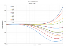
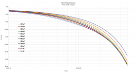
A bit more data on the Edcor Zobel. The measurement set-up is shown in post #716. I used Edcor transformer #3. R5 is kept at 10K, C1 is varied from 100pF to 1300pF, values shown as measured. The first plot is freq response from 1kHz - 50kHz, the second is the Bode phase plot. I haven't tried and of these values in a completed amplifier. I think measuring square wave response as Mark discusses in post #717 and shown in Whitlock's publication are my next step.
@Mark Johnson - thanks very much for the references. Both the Whitlock publication and the Schaum's guide are great. Hopefully the math won't be a problem....
Phil
@Mark Johnson - thanks very much for the references. Both the Whitlock publication and the Schaum's guide are great. Hopefully the math won't be a problem....
Phil
Attachments
Last edited:
I think I prefer (10K series 502pF) but ... will wait to see whether the frequency response is more sensitive or less sensitive to changes in the resistor value, than changes in the capacitor value. Will also wait to see whether the transient response (output damping with unit step input) has a different sweet spot than frequency response. If so then a compromise may be called for.
Hello
I'm thinking of getting into making the M2X version Ishikawa and Mountain View.
AND I have some questions and a remark of understanding.
What is RV1 5K serving on the main board. If it adjusts bias or offset, how does one measure it?
What is the CB3 capacitor on the main board for?
My remarks:
It would be nice to specify the component values in the build notes and in the forum when 2 component have the same name.
For example there are 2 RV1: "RV1 5K" on the main board and "RV1 200K" on the ischikawa board
Example 2: There are 2 capacitors C1 "C1 680pf" on the main board and "C1 220uF" on the ischikawa board.
My current system:
Zen Vp1 amp
pre amp BOZ
rear load speaker
EMS FERTIN full-range LB8 MKII loudspeaker
Thanks you.
Last edited:
The remaining parts for assembling the Mountain View input modules arrived yesterday so I was able to swap out the Ishikawas. Wow! The organic, warm mid-range that I loved from the Ishikawa was even better with the Mountain View. Images were even more three dimensional with a move vivid sense of space -- similar to my AES (Cary) 300B SET, but with greater bass extension and authority and a more extended and relaxed top end. I must say that this is my favorite module, so far.
I have parts coming in later this week for the Austin modules. I've built several headphone amps with Pete Millett's diamond buffers and liked the sound. My guess is the BJT diamond buffers will be less colored than the class A, single-ended Mountain View. In the meantime, I'll be digging the Mountain View's sweet warmth!
I have parts coming in later this week for the Austin modules. I've built several headphone amps with Pete Millett's diamond buffers and liked the sound. My guess is the BJT diamond buffers will be less colored than the class A, single-ended Mountain View. In the meantime, I'll be digging the Mountain View's sweet warmth!
- Home
- Amplifiers
- Pass Labs
- The diyAudio First Watt M2x