Measuring DC offset with an 8 ohm or 4 ohm dummy load is the most conservative approach, in my opinion. When the amplifier's output offset is nonzero, it's delivering DC current into the load. Which means the output transistors are not operating at their equilibrium. In my opinion this is a better test because it is more difficult.
Also don't forget that some* amps oscillate with no output load. Measuring DC offset on an oscillating amplifier is a frustrating exercise. (*perhaps not the amps Nelson Pass publishes here)
Then there's the subtle matter of dialing in the offset while jockeying the mains voltage plus or minus seven percent on a Variac.
... Moffet Field. I've built a 24 mA version (pic below) but I'm shooting for 30 mA with another set of JFETs ...
VERY nice! Congratulations, Phil. The grand-daughter board with pluggy wires is way off the beaten path. Kudos for creativity.
A dummy load is always a good idea.
well , call me a Sissy and Weakling , both in same time ..... but to me - having dummy load while setting output DC offset is same as dragging foot-long rock around the neck , while diving for pearls
nothing wrong if offset is initially low (which is in M2 , presumably) , but someone can adopt same technique while chasing offset on F5 or Aleph , so Gray Smoke is inevitable
however , not mine mosfets , not mine resistors ....... but I'll certainly stumble on few more threads about solving what could be avoided , without using unnecessary and potentially harmful steps
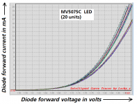
Current - Voltage behavior of MV5075C LED used in Mountain View
I just pulled twenty brand new MV5075C LEDs out of their shipping bag and put them on the curve tracer. These are the infamous "do not substitute" LEDs used in the bias network of the Mountain View daughterboard.
I don't exactly know why the data clusters in two groups with a gap between. Maybe it's just a coincidence, an artifact of examining too few (20) samples. Or maybe it's more sinister. I have no idea.
Hopefully this data is more useful than the min,max guaranteed never to exceed numbers on the datasheet.
_
Attachments
Or maybe it's more sinister. I have no idea.
White spy Vs. Black spy.

Last edited:

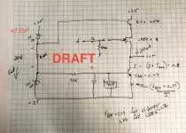
The Moffet Field seems to be running fine at 30 mA. I'm using 3 - J112 jfets selected for about 12.5 mA Idss and CCS adjusted for 80% of the total. The BJT's are pretty toasty and should get little heat sinking or replaced. I don't show C1, C2 or C3 in the schematic and I think I'll add a 2.2uF cap across the top zener (formerly D2). Square wave at 1kHz, 1 Vp-p is visually perfect and stable. Offset is about 100mV as built. It fits very nicely on the existing Mountain View board. Old D2 and the 6.2k resistor (R1) are on the bottom of the board.
Phil
Phil
Attachments
Looks terrific Phil! I like your bias dropper ZTX device, it's cute.
Just in case the beta of the NPN current sink is low, you might want to consider an increase of the current flowing in the two zeners, so you can siphon out some more milliamps & send them over to the base node including VREF diode.
BTW I never imagined actually building a Moffett Field modification using the existing MV PCB; I just assumed a brand new layout. Getting it all to work on the old board is quite an accomplishment. Bravo!
thanks Mark! R1 is now 3k. Thank you for the tip. I'll put a 600R load on it and post some more data and pics of the board. The mods are easy - one small hole in the middle of the pads for D2 and 2 parts on the bottom so I hope others try it.
response of the audio signal of the 5 versions?
Hello. Hello.
one question that does not seem to have been addressed is the question of the phase inversion of the input signal with respect to the output signal in the different versions:
ishikawa: inversion or, no phase inversion of the input signal
mountain view:
Tucson:
Norwood:
Austin:
Should the polarity of the speaker connections be changed if the phase is reversed?
I hope that my translator has translated my thoughts well.
Thank you. Thank you.
All five M2x daughterboards have the same output phase, the one chosen by Nelson Pass when he designed the original First Watt M2 amplifier.
In need of some guidance
The amp was working perfectly with bias at 1.8A and offset adjusted to a stable 1mV. I built up the MtnView daughter board and tested that with an offboard power supply and it tested at what appeared to be normal. After I had pulled out the Norwood (which was sounding really great) and dropped in the MtnView the right channel came up with an offset of 500 to 800mV which I was only able to pull down to 180mV and it showed some sort of fluctuation - almost like it was oscillating. The LED on that MtnView was also flickering. I shut it down and swapped the daughter boards between channels and the right channel once again showed the same behavior but offset was now 800mV-1.2V. The bias seemed rock solid on both amp boards. It is really difficult to adjust offset - very little movement with adjusting the pot.
edit - left channel with the MtnView board that had been flickering is rock solid with 1mV offset.
I checked all connectors - all making good contact, I reflowed all the solder points on the affected board to make sure something spurious had not developed coincidentally.
My suspicion is that the little trimmer is not adjusting as it should but before I replace it, I was wondering if there is anything else that I should be looking for?
thanks..dB
If the little trimmer on the amplifier main channel board ("RV1" on schematic) has indeed failed, and if that is the cause of misbehaviors you are observing,
then the misbehaviors are expected to continue with ALL daughter cards. Even with the Norwood cards. Even when you swap the two Mountain View cards (left swapped with right).
On the other hand, if there is a problem with one of the two Mountain View cards, and no problem with the amplifier main channel boards: we would expect to see misbehavior when that one particular Mountain View board is installed, and no misbehavior when it is replaced.
_
Attachments
thanks Mark
yes - I didn't detail that little part of my experimenting - when I put the Norwood back into the faulty amp board, I was again seeing large amounts of dc offset which could not be adjusted on the impacted amp board.
The problem does not follow any particular daughter card as they all work normally in the still functioning amp board.
Thus my assumption that something on the amp board itself was causing problems. As it biases normally I would work on the premise that the biasing components and the output devices are not at fault and that leaves the trimmer RV1 as the most likely element.
I did try and measure the effective resistant while in the circuit and after many many turns, it does change the total resistance a little but nowhere near what I would expect - I just have little trust measuring resistance when still in the circuit
I will get a replacement ordered and try that
..dB
Yes it sounds like the problem is with the one main amplifier board and not with any of the daughter cards.
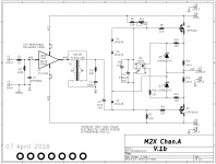
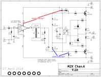
After you remove the board from the heatsink, you can use your multimeter on "buzz" continuity test, to see whether each end of R6 connects where it should, to see whether each end of R7 connects where it should, to see whether each terminal of RV1 connects where it should. Example probing ideas attached.
You could touch one of your continuity tester probes to the metal lead wire on the body of R6 {not the PCB trace, the actual lead of the resistor itself} and touch the other probe to the VCC bolt of the daughter card mount. If R6 is correctly soldered and if the PCB copper is intact, you tester should say: Yes, Continuous.
Test both pins of R6, both pins of R7 (one way to test its top pin is shown in blue), all three pins of RV1, and pins 4&5 of the optoisolator. Prove to yourself it's connected the way it should be.
edited- don't forget to buy the same resistance value on the new trimmer, as on the old. If your board has (R6=47K, RV1=5K) then get another 5K trimmer. If your board has (R6=37K, RV1=20K) then get another 20K trimmer.
Attachments
Last edited:
thanks will check this out - and yes, I am using the 37K / 20K combination.
I switched the optoisolator between amp boards and they seem to work , so device is operational. I did have to double check the orientation.
..dB
I switched the optoisolator between amp boards and they seem to work , so device is operational. I did have to double check the orientation.
..dB
I little construction tip: I’ve gotten in the habit of soldering all parts (including trim pots) as far off the board as possible. This makes it easy to remove a part by just clipping it’s leads and then desoldering them from the board. Desoldering three pin parts that are snug to the board can be a bugger.

Desoldering three pin parts that are snug to the board can be a bugger.
just flood them - they drop out with little or no effort and you can have a mechanically secure trimpot on the board - at least that is my preference
- Home
- Amplifiers
- Pass Labs
- The diyAudio First Watt M2x