Ok....I see. You used a smd PCB and soldered it on to a DIP8 socket. I will look at Sjöström Audio......sounds Swedish…….
I made a measurement on 3 different Nichicon 10 uF capacitors
Hi MEPER, congratulations on deciding to make some measurements yourself! A brave decision which I admire very much.
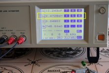
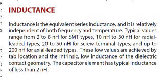
I find one aspect of your photographs a bit confusing, see yellow box in Figure 1 below. It's hard to understand how a 10uF electrolytic capacitor could produce a reading in the millihenries (1 x 10^-3) ?? Usually electrolytic capacitor measurements give an Equivalent Self Inductance ("ESL") in the nanohenries (1 x 10^-9).
Figure 2 is a snip from the document "Aluminum Electrolytic Capacitor Application Guide" by Cornell-Dubilier, a manufacturer of high quality electrolytic capacitors. It says nanohenries not millihenries.
Also I had some fun last year measuring electrolytic capacitor ESL myself, using a slightly weird mixed-signal (analog + digital) test jig I built:
Measuring the "ESL" inductance of electrolytic caps (at 10 MHz!)
Again the results were nanohenries, not millihenries.
Could you explain a little bit, why your measurements say millihenries? That is about a factor of 10^6 (one million times!) different than expected? Thank you!
Attachments
to MEPER #1821
Sjöström Audio - Home
Per Anders Sjöström ( I think he is also a member here) has also some other nice gadgets....
Greets
Dirk
Sjöström Audio - Home
Per Anders Sjöström ( I think he is also a member here) has also some other nice gadgets....
Greets
Dirk
Remember that all five of the input stage daughter cards shipped with M2x, including Tucson, implement a "buffer", which is a noninverting amplifier with a gain of 1.0.
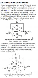
When we look at the manufacturer's datasheet for the Analog Devices AD797 we see the information copied below.
It tells AD797 customers that if they want to operate AD797 as a noninverting amplifier with a gain of 1.0, they must add two resistors R1 and R2, which are not included on the Tucson PCB. And if you want best response flatness, you should also install capacitor CL, and then experiment with its value "for best results".
This is not impossible but it is cumbersome. Since the Tucson PCB does not include "footprints" for any of R1, R2, or CL, you must add them as "bodge" components, after cutting the appropriate PCB traces. It is not impossible, it can be done, but I myself will not be trying it any time soon.
_
Attachments
to MEPER
At Per Anders Sjöströms website you find the adapters under the name:
ADP01 - ADP04
Greets
Dirk
At Per Anders Sjöströms website you find the adapters under the name:
ADP01 - ADP04
Greets
Dirk
Hi MEPER, congratulations on deciding to make some measurements yourself! A brave decision which I admire very much.
Figure 2 is a snip from the document "Aluminum Electrolytic Capacitor Application Guide" by Cornell-Dubilier, a manufacturer of high quality electrolytic capacitors. It says nanohenries not millihenries.
Also I had some fun last year measuring electrolytic capacitor ESL myself, using a slightly weird mixed-signal (analog + digital) test jig I built:
Measuring the "ESL" inductance of electrolytic caps (at 10 MHz!)
Again the results were nanohenries, not millihenries.
Could you explain a little bit, why your measurements say millihenries? That is about a factor of 10^6 (one million times!) different than expected? Thank you!
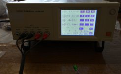
I looked in the manual for the tester to see if there was any hint. The examples where capacitance was measured Ls was not selected. Up to 4 parameters among many can be selected on screen for a measurement. The tester does not know which component tested. It tries to match to an equivalent circuit by doing "some" measurements. If I go down to 50 Hz Ls shows 900 mH and if I go up to 100 kHz Ls is about 300 nH (picture). So think more info is needed on how the tester measures the different parameters. Maybe Ls is not "meaningful" for testing larger capacitors. As far as I could see voltages/current was within limits.
They do write this:
Rs effective resistance in series equivalent circuit mode (Ω)=ESR *2
So think Rs can be "trusted". I also thinks it matches data sheets from previous measurements.
The PDF manual was to large to be attached…….. 🙂
Attachments
Wow! Nice build Manniraj, Very trick meters. Where did you get them? Any possibility of a closer pic of the meters? I love that “classic” meter look 👏🏻
Thanks, I got the cabinet from China and here is the link to the VU meters. 2PCS hifi Amplifier VU meter DB level Header Lamp indicator Peak+1PC Drive board-in Amplifier from Consumer Electronics on Aliexpress.com | Alibaba Group
Congratulations two times! First for your success, second for your bravery in making your own daughter boards. Good on ya!
Thanks Mark, I was worried about the hum with the EDCOR trafos on the amp boards. But surprised that the amp is just absolutely hum free on my 87db Frugal Horns. In fact I have some amount of hum on my VFET2 build but none in this and I did not do anything extra that some of the members here have experienced with the power transformer interfering with the EDCORs. May be I am lucky but I just used a CL-60 thermistor from the PSU ground in series to the chassis.
I looked in the manual for the tester to see if there was any hint. The examples where capacitance was measured Ls was not selected. Up to 4 parameters among many can be selected on screen for a measurement. The tester does not know which component tested. It tries to match to an equivalent circuit by doing "some" measurements. If I go down to 50 Hz Ls shows 900 mH and if I go up to 100 kHz Ls is about 300 nH (picture). So think more info is needed on how the tester measures the different parameters. Maybe Ls is not "meaningful" for testing larger capacitors. As far as I could see voltages/current was within limits.
They do write this:
Rs effective resistance in series equivalent circuit mode (Ω)=ESR *2
So think Rs can be "trusted". I also thinks it matches data sheets from previous measurements.
The PDF manual was to large to be attached…….. 🙂
A bit more on how it measures. It seems to be a simple series or parallel circuit the tester tries to "adapt to". For larger capacitors the series values are recommended…..like Cs, Rs, Ls etc....Cp, Rp, Lp can also be selected to be viewed.
The 3522-50 unit analyses the test sample in terms of a pure inductive
component (L), an equivalent circuit construction composed of a pure
capacitive component (C), and a pure resistive component (R), and calculates
as though these components were connected in series, or alternatively
connected in parallel. Therefore, it is possible for the user to select either a
series equivalent circuit mode or a parallel equivalent circuit mode for this
conceptual connection together of these L, C, and R components.
I've always felt that the reported differences in "listening pleasure" between one capacitor and another, has got to be something other than mere differences in measured ESR and/or ESL.
If the only significant sonic variable were ESR, then we could connect two identical capacitors in parallel, which reduces ESR by a factor of 2X, and so we should get a 2X improvement in "listening pleasure". But nobody who has tried this, reports any improvement in listening pleasure at all.
If the only significant sonic variable were ESL, then shorter capacitor leads would give lower inductance (roughly 10 nanohenries per centimeter of length) and improved listening pleasure. But audiophiles routinely install large expensive film capacitors with 4 cm leads on each end, and report subjectively huge improvements in listening pleasure. The parallel capacitor experiment works for ESL too: connect two identical capacitors in parallel, which reduces ESL by a factor of 2X, but does it improve listening pleasure by 2X? Nobody who has tried this, reports any improvement in listening pleasure at all.
Whether your meter accurately reports ESL and ESR, I don't know. I very much doubt it accurately reports "listening pleasure".
Whether your meter accurately reports ESL and ESR, I don't know. I very much doubt it accurately reports "listening pleasure".
Invent that meter and you'll be rich!!!!!!! 😀😀😀
But why pay more for an "audio cap" if an industrial type is closer to an "ideal" capacitor and no one can hear difference anyway?
By the way…...my component source RS-Components does not have IRFP240 (they do have IRFP9240). But they have IRFP244 which by looking at the data sheet could work instead of IRFP240? …..IRFP244 seems to be an upgraded 240?
By the way…...my component source RS-Components does not have IRFP240 (they do have IRFP9240). But they have IRFP244 which by looking at the data sheet could work instead of IRFP240? …..IRFP244 seems to be an upgraded 240?
The chief designer of preamp products at Pass Labs, Mr. Wayne Colburn, gave a talk at Burning Amp 2018 which is on Youtube and which Google can locate for you. In the lecture he briefly mentioned, en passant, that one particular line of electrolytic capacitors by one particular manufacturer, gave lower measured distortion than all others. And that was the capacitor make and model that he used in the project he was describing. You can watch the video, it's less than an hour long, and find out what other gems and gold nuggets he casually dropped during the talk.
Remember that all five of the input stage daughter cards shipped with M2x, including Tucson, implement a "buffer", which is a noninverting amplifier with a gain of 1.0.
When we look at the manufacturer's datasheet for the Analog Devices AD797 we see the information copied below.
It tells AD797 customers that if they want to operate AD797 as a noninverting amplifier with a gain of 1.0, they must add two resistors R1 and R2, which are not included on the Tucson PCB. And if you want best response flatness, you should also install capacitor CL, and then experiment with its value "for best results".
This is not impossible but it is cumbersome. Since the Tucson PCB does not include "footprints" for any of R1, R2, or CL, you must add them as "bodge" components, after cutting the appropriate PCB traces. It is not impossible, it can be done, but I myself will not be trying it any time soon.
_
Thanks Mark for this info.
... Mr. Wayne Colburn gave a talk at Burning Amp 2018 ... one particular line of electrolytic capacitors by one particular manufacturer, gave lower measured distortion than all others ...
If you ever found yourself wondering why the unusual comment text on the M2x "Austin" daughter card schematic diagram was written that way, including the very serious word PREFERRED, now you know.
I did solder in the Green Nichicon in M2X boards and bypassed it by a small Wima MKP at the underside of the PCB (just for fun). Don't know if it is that video Wayne seems to like the Green Nichicon and the grey MKPs…….but I assume so. Think it was the Whammy video (will check later). But maybe the blue BT industrial Nichicon (which measures better) could give similar good results.
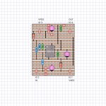
With the recent discussion about opamps for the Tuscon IPS, here is an updated layout of the through-hole version on veroboard. There are a few DIP-8 opamps that appear interesting, including the MUSES03, OPA134, and the AD797, besides the OPA604. This board includes provisions for the resistors and capacitor that are recommended to operate the AD797 at unity gain. For other opamps, the 10pF cap can be omitted, but the resistors are probably Ok to leave or replace with jumpers. There is room for both an electrolytic and film bypass cap for the output AC coupling, but if the opamp has sufficiently low* input offset voltage, those may also be replaced by a jumper.
* I like to see less than 1 mV input offset voltage before I omit the output coupling cap.
* I like to see less than 1 mV input offset voltage before I omit the output coupling cap.
Attachments
- Home
- Amplifiers
- Pass Labs
- The diyAudio First Watt M2x