Just finished my M2X, my first module being Ishikawa with C1 coupled.
After some testing and measurements, i found out that both channel i have 47mV and 21mV just before the C1 cap. Do i really have to matched the Jfets further to get even lower DC ?
Is this figure safe to bypass the C1 entirely ?
After some testing and measurements, i found out that both channel i have 47mV and 21mV just before the C1 cap. Do i really have to matched the Jfets further to get even lower DC ?
Is this figure safe to bypass the C1 entirely ?
New M2x coming online
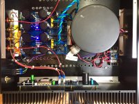
I just did a simple power on test for one channel of my new M2x. Looking good so far. Transformer is an Antek AS-4218, shielded by one of their 400VA steel cases. I decided to try a discrete rectifier implementation this time, using Vishay FEP30DP-E3/45 fast recovery diodes. Power rails loaded by a single channel are right at +/- 23.0V for now. Unloaded voltage was 24.6V.
The chassis is a 2.5U, 400mm deep ebay special. I figured its heat capacity would be sufficient, but added an aluminum L bracket along the base of each heatsink to better spread the heat between the two pieces on each side. Voltage across the source resistors indicates 1.31 Amps through the output transistors, and the heatsink was just warm to the touch after a half hour of warming up.
Attachments
to TungstenAudio
Looks like a very nice build. Some more pics?
Enjoy the beautiful sound!
Greets
Dirk
Looks like a very nice build. Some more pics?
Enjoy the beautiful sound!
Greets
Dirk
Good idea on the L-bracket and on the (DIY?) perforations in the bottom chassis plate. It must have been painful to find length1 brass male-female M3 spacers to fit the flat part of the heatsinks, and also length2 which fit the recessed area where the heatsink halves abut. Kinda weird not to center the power amplifier boards with left margin == right margin, so the left output transistor has the same amount of heatsink as the right output transistor. But the arrangement in the pic does move the Edcor another inch farther away from the power toroid.
I bet the socket you used for the 4N35 cost more than the optoisolator itself.
Funny that every single Ishikawa posted in this thread, appears to include the Not Designed By Nelson Pass coupling capacitor (220uF C1).
_
I bet the socket you used for the 4N35 cost more than the optoisolator itself.
Funny that every single Ishikawa posted in this thread, appears to include the Not Designed By Nelson Pass coupling capacitor (220uF C1).
_
Last edited:
Looks great! Looking forward to your listening impressions once both channels are working.
Some people have reported Hum before rotating the transformer vertically. I'm interested to see if the shield is enough to prevent the need of setting the big toroid vertically.
Good luck!
Rafa.
Some people have reported Hum before rotating the transformer vertically. I'm interested to see if the shield is enough to prevent the need of setting the big toroid vertically.
Good luck!
Rafa.
I think the base question is what effects would this have? (either positive or negative?) And there is clear indication of negative effects if you omit it (more on this later).... Funny that every single Ishikawa posted in this thread, appears to include the Not Designed By Nelson Pass coupling capacitor (220uF C1).
I think that some people here can 'take decisions', do measurements, venture conjectures as to what is best. Others, like me, are just limited to building what we are told to build how we are told to build it: if you say include the Cap, i'd put it in, if you say leave it out, i'd leave it out.
But when you get a phrase like: "Want to guarantee there’s no DC flowing through the auto dormer and saturating the core? Install C1" (as posted by 6L6 on page one instructions), it leaves little room to question this component. Read it the other way around: "If you wan't to have DC flowing into the autoformer and saturating the core...", well, who would want that? 😱
Also, I have read several times in different posts the phrase: Papa Nelson has closer-to-specs parts than most. His parts bin allows for getting the perfect value / matching to avoid those minor corrections. Those of us who purchase the 2 resistors that are going to populate the PCB, have little choice but to plan for some corrections.
If we could buy 30 of each and just pick the best matching / measuring parts, then that would be great, but that is not the reality for some of us.
So, if there is more info on C1 than this very clear warning that, as I read it, leaves very little room to chose to keep it out, please share it with the group! 🙂
Every one of the hundreds of people who built the "M2 Clone" from Tea-Bag boards, built the original Nelson Pass circuit. Tea-Bag followed the Official M2 Schematic when laying out the M2 Clone board. There's no 220 uF capacitor on the schematic, so there's no 220 uF capacitor on the PCB. No footprint, no capacitor on any of the builders' M2 boards.
These builders used JFETs they bought from the diyAudio store, or from Spencer at FETaudio, or from punkydawgs on eBay, etc. But they assuredly did not use JFETs originating from the magical stockroom at Pass Labs.
The overwhelming majority of builders are deliriously happy with their M2 Clone. Which has no C1.
It amuses me that people choose Ishikawa because the original designer's original circuit must clearly be superior ... and then they add something not present in the original design. It's a lesson in psychology, that is worth learning.
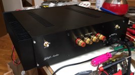
Took a couple quick and dirty pics of the amp while both channels are cooking. Rail voltage has dropped slightly to +/- 22.6V, and bias current is holding steady at 1.31 Amps. Output offset continues to drift slightly, but remains in an acceptable range, thanks to an unmentionable procedure using component values that shall not be named. 😀
The extra holes that needed to be drilled in the bottom plate are doing their job, as the power rectifiers are giving off a noticeable amount of heat. The main heatsinks do have a detectable thermal gradient from front to back, and the front plate is also warm to the touch. My plan was to have the entire case act as a heat sink, and this seems to be working well. So far the whole case is just warm to the touch, with warmer spots where the MOSFETs are bolted on. The hottest areas are still comfortable to touch indefinitely. I'm using 1.78 mm thick ceramic thermal interface spacers and 10 mm brass standoffs to elevate the main PCBs above the heatsinks.
I chose to insert the C1 output capacitors in the Ishikawa IPS to allow for some deliberate tinkering of the JFet offsets. I have a distortion analyzer and a 'scope, and plan to play with H2 content by adjusting RV1 when feeling sufficiently motivated at some later date. In the meantime, I didn't have any 200Ω pots to install, so the output caps are there for peace of mind.
Attachments

I just did a simple power on test for one channel of my new M2x. Looking good so far. Transformer is an Antek AS-4218, shielded by one of their 400VA steel cases. I decided to try a discrete rectifier implementation this time, using Vishay FEP30DP-E3/45 fast recovery diodes. Power rails loaded by a single channel are right at +/- 23.0V for now. Unloaded voltage was 24.6V.
The chassis is a 2.5U, 400mm deep ebay special. I figured its heat capacity would be sufficient, but added an aluminum L bracket along the base of each heatsink to better spread the heat between the two pieces on each side. Voltage across the source resistors indicates 1.31 Amps through the output transistors, and the heatsink was just warm to the touch after a half hour of warming up.
Nice neat build! 👏🏻
Took a couple quick and dirty pics of the amp while both channels are cooking. Rail voltage has dropped slightly to +/- 22.6V, and bias current is holding steady at 1.31 Amps. Output offset continues to drift slightly, but remains in an acceptable range, thanks to an unmentionable procedure using component values that shall not be named. 😀
The extra holes that needed to be drilled in the bottom plate are doing their job, as the power rectifiers are giving off a noticeable amount of heat. The main heatsinks do have a detectable thermal gradient from front to back, and the front plate is also warm to the touch. My plan was to have the entire case act as a heat sink, and this seems to be working well. So far the whole case is just warm to the touch, with warmer spots where the MOSFETs are bolted on. The hottest areas are still comfortable to touch indefinitely. I'm using 1.78 mm thick ceramic thermal interface spacers and 10 mm brass standoffs to elevate the main PCBs above the heatsinks.
I chose to insert the C1 output capacitors in the Ishikawa IPS to allow for some deliberate tinkering of the JFet offsets. I have a distortion analyzer and a 'scope, and plan to play with H2 content by adjusting RV1 when feeling sufficiently motivated at some later date. In the meantime, I didn't have any 200Ω pots to install, so the output caps are there for peace of mind.
Well done! Different rear layout than most. Which chassis did you use?
I think you have done an incredible service to the DIY audio community with the swappable boards and specially providing alternatives to the ever-harder-to-get Toshibas. I think you should be (and are) really proud about this contribution....It amuses me that people choose Ishikawa because the original designer's original circuit must clearly be superior ... and then they add something not present in the original design. It's a lesson in psychology, that is worth learning.
But, with all due respect, I don't understand why you feel the need to put down or ignore everyone that favors the Ishikawa board: you continuously push away anyone asking anything about that board basically saying "go ask in the M2 thread", when it will probably take you less time to actually help those that have believed and adopted for your idea and take on this version of the amp. You kind of 'mock' those that choose to add C1 in spite of the designers original design. And to everyone that has an opinion on the sound of your boards you usually answer with "build another one", or "build the Ishikawa and go ask elsewhere".
While I applaud your iniciative here and think you gave an incredible contribution to the DIY community, I often find your replies here a bit bitter and off putting to people actually looking for help, input, or just sharing their venture with others that are navigating the same waters.
If I'm alone in felling like this, I apologize. But if this insight may help others not feel this 'wall' built around those choosing the original board, I'm sharing my view.
Best,
Rafa.
I decided to go ahead, removed trimmer & C1 then install the jumper link, immediately i was rewarded with better clarity and tighter bass.
Thanks, everyone for making this possible and its music time !
At the meantime, will start populating the rest of the daughter cards.
Thanks, everyone for making this possible and its music time !
At the meantime, will start populating the rest of the daughter cards.
Every one of the hundreds of people who built the "M2 Clone" from Tea-Bag boards, built the original Nelson Pass circuit. Tea-Bag followed the Official M2 Schematic when laying out the M2 Clone board. There's no 220 uF capacitor on the schematic, so there's no 220 uF capacitor on the PCB. No footprint, no capacitor on any of the builders' M2 boards.
These builders used JFETs they bought from the diyAudio store, or from Spencer at FETaudio, or from punkydawgs on eBay, etc. But they assuredly did not use JFETs originating from the magical stockroom at Pass Labs.
The overwhelming majority of builders are deliriously happy with their M2 Clone. Which has no C1.
It amuses me that people choose Ishikawa because the original designer's original circuit must clearly be superior ... and then they add something not present in the original design. It's a lesson in psychology, that is worth learning.
That’s absolutely NOT the reason I chose the Ishikawa. I chose it cause I wanted to get an idea of what the original sounded like and a point of reference for when/if I wanted to try another front end.
I chose the Ishikawa because its the easiest one to build to me, it looked so bare without C1 and trimmer!
An old man like me will probably start pulling my hair off while trying to populate rests of the other SMD daughter cards.
An old man like me will probably start pulling my hair off while trying to populate rests of the other SMD daughter cards.
I'm getting to where I cringe every time I see the acronym SWMBO.
I'm still married to my 1rst wife and do understand that compromises are needed.
As does she.
However, SWIBO (she who is being obeyed) getting a whole house wireless system and you a corner with a set of headphones is not only inequitable, it's demeaning.
Ok, I really didn’t expect that sort of response. My original post was actually meant to be a little tongue in cheek and dosed with a heavy helping of sarcasm. But I appreciate that it may not come across particularly well in text on a forum website. My apologies to any/all that may have been offended. But really????
Note to self.....Must try harder not to offend the delicate sensitivities of others.
This cultural gap can be a tricky thing to bridge sometimes.
Back to the technicalities..... I’ve decided to build the Whammy for now as a headphone amp. It’s almost done, but going back and forth on whether or not to try using a relay controlled attenuators for volume control rather than the pot. The M2x parts are safely stored away in a box for another rainy day.
Actually I'm thrilled when folks build an M2x and even more thrilled when they build and audition two or more input daughter cards. I'm glad we offer the Ishikawa board and even more glad we include two build options on that board which are not present in the Official M2 Schematic (those would be C1 and RV1). In my opinion, these extra choices are good and choice is not scary.
Feedback from actual builders does indicate that offering the builder more than one design choice (option), is welcome and pleasing to some constructors, but definitely not all. Providing six different design choices in the PCB shipment seems to encroach into the territory of "overwhelming" in some cases. If you count SMD-Tucson (OPA1611) separately from ThruHole-Tucson (OPA604) there are six possibilities. {BTW people report these two don't sound the same -- if you give any weight to the listening preferences and sonic impressions of others}
Maybe the right way to offer a PCB package to BOTH "just tell me what to do and don't ask me to decide" timid people, while at the same time also offering the same PCBs to "this is my fourth First Watt amp, I'm brimming with confidence" people, is to assign different names having different connotations, to the various possibilities. For example the names might be: Starter, Advanced, Expert. Or perhaps Easy, Difficult, Challenging. Maybe even Good, Better, Best as they labeled products in the Sears mail order catalog decades ago.
Offer for sale the lowest tier, then make the next two tiers an extra-cost, extra-effort, extra-skill option which builders might, or might not, select. Even if the extra cost of tiers 2 and 3 is only one dollar, the perception of additional complexity and OMG-I-must-decide-something would probably mean that timid people would select the bottom tier. The tell-me-what-to-do tier. And these people would be happy! Meanwhile the supremely confident builders would have tier 2 and tier 3 options to experiment with. They would be happy too.
But, with all due respect, I don't understand why you feel the need to put down or ignore everyone that favors the Ishikawa board: you continuously push away anyone asking anything about that board basically saying "go ask in the M2 thread", when it will probably take you less time to actually help those that have believed and adopted for your idea and take on this version of the amp. You kind of 'mock' those that choose to add C1 in spite of the designers original design. And to everyone that has an opinion on the sound of your boards you usually answer with "build another one", or "build the Ishikawa and go ask elsewhere".
I think you are misunderstanding what Mark is getting at, the M2x is all about choice and experimentation, and the ability to build it exactly as designed by Nelson is one of those choices. That you can venture further with simple or more complicated choices/modifications, such as trying the coupling cap in front of the autoformer is also something you can do. (or not)
Also, you need to realize something that he and I are both actively doing - specifically, we (Mark and I) are not talking about our impressions of the sonics of the various cards. That's for you to do. If I were to come out and say "Holy cow!! The Barcelona daughter card is absolutely the best, build it first and don't even bother with the rest!" A significant majority of people would do that, much to the detriment of the whole idea behind the swappable cards.
((This has led to a not insignificant gnashing of teeth when considering what daughtercard parts the store would include in a parts kit. (Yes, there will be one, hopefully in the not too-distant future. When exactly? No idea, we're really busy lately with a ton of new stuff... 🙂 ) It's not cost-effective to include parts for all, and if we were to choose just one, that will also hinder experimentation... but regardless which are chosen, there's going to be a bias towards (maybe bad, maybe good, don't know) because a choice has already been made regarding them... ))
Anyway, the entire point of what you are perceiving as Mark's rudeness is just him encouraging people to get out there and try it yourself and make up your own mind about what sounds best. Sometimes tone doesn't come through well in forum posts. He means well, and really does just want people to try.
To all you M2X-builders:
try the different input cards (as I did) and make your own choice what sounds best to your ears! Everybody has a different system (loudspeakers, sources,...),
everybody is listening to different kinds of music,....
So: What is right/best or what is wrong/worst?
Nobody can answer this. I can't. 😀
Greets
Dirk
Has anyone performed any objective performance measurement tests on this amplifier yet? If so which post has it?
Cheers,
Alan
Cheers,
Alan
To all you M2X-builders:
try the different input cards (as I did) and make your own choice what sounds best to your ears! Everybody has a different system (loudspeakers, sources,...),
everybody is listening to different kinds of music,....
So: What is right/best or what is wrong/worst?
Nobody can answer this. I can't. 😀
Greets
Dirk
Tried it with the Tucson board fitted with the Burr-Brown OPA604AP * pin DIL IC. Auditioned with two different sets of loudspeakers, three different pre-amps and a very wide genre of music. Sorry, didn't like it at all. 🙁
Cheers,
Alan
- Home
- Amplifiers
- Pass Labs
- The diyAudio First Watt M2x