Would it be easier to get an encapsulated transformer? I have no hum on 98db speakers only using an encapsulated transformer and the edcor fully exposed
I intend to find out. I have a quote from Toroidy for an encapsulated transformer, and will order soon. The reason being is I'm having a buzz/hum coming from both channels after switching from the M2 (Tea-Bag boards) to the M2x with Norwood daughter card. With the M2 I had an audible buzz/hum only with my ear right up to the speaker, now with the M2x boards it's audible 2-3 feet away. if someone will explain how to measure it electronically that would be appriciated (I probably have the equipment to do so).
I intend to find out. I have a quote from Toroidy for an encapsulated transformer, and will order soon. The reason being is I'm having a buzz/hum coming from both channels after switching from the M2 (Tea-Bag boards) to the M2x with Norwood daughter card. With the M2 I had an audible buzz/hum only with my ear right up to the speaker, now with the M2x boards it's audible 2-3 feet away. if someone will explain how to measure it electronically that would be appriciated (I probably have the equipment to do so).
Testing for supply ripple was/is beyond my skill level. I’m currently in the process building a work bench (just got a 465B and repaired a HP 204C that was given to me) but I brought both my amps to a friend who’s been building and repairing amps for decades. He measured mine and the both came out good. I think he measured the input signal, then measured the output signal and took the difference. Something like that but don’t quote me on that ha
You can take a DMM and set it to AC at the highest resolution (most sensitive setting) and measure the output with shorted inputs. Your reading should be way below 1 mV. A good power amp should not show more than 0.2 mV of noise at the output. It is probably difficult to get much below 100 uV of noise.
I have a very very long run from preamp to amp and would like a matching balanced T before the M2x.
I am using a 4p1L to a LL1671 with balanced output but want the M2x to have a Input T as well.
Does the attached image make sense?
I know I could just keep R1 and R2 and slap that inputT right infront but could I do what I put in the image and remove R1/R2 and place each pole of the T output to the Q3/Q4 directly.
center of secondary would be grounded of course(maybe place the 100K R there too?
Attachments

I recommend you check with the much larger number of people who have built the First Watt M2 amplifier using the original Nelson Pass input circuit (no daughter card) with Toshiba JFETs:
I think you will need to swap 7 & 10 (same phase - see F6, note opposite phase) then connect 7 & 9 to 0V.
On second thoughts, parralell the output windings to keep the JFET gates tied together.
On second thoughts, parralell the output windings to keep the JFET gates tied together.
Last edited:
Let me rephrase the question because I did that in a rush this morning between meetings.
Attached is a new image.
Can I remove R1 and R2? I know they set a load but wouldn't the Transformer do that instead. I know there is losses and some people will say why would you do this and add distortion device. But I have over 40 ft from pre to amp so I need that CMRR.
Attached is a new image.
Can I remove R1 and R2? I know they set a load but wouldn't the Transformer do that instead. I know there is losses and some people will say why would you do this and add distortion device. But I have over 40 ft from pre to amp so I need that CMRR.
Attachments
Let me rephrase the question because I did that in a rush this morning between meetings.
Attached is a new image.
Can I remove R1 and R2? I know they set a load but wouldn't the Transformer do that instead. I know there is losses and some people will say why would you do this and add distortion device. But I have over 40 ft from pre to amp so I need that CMRR.
R1 and R2 are there for establishing proper conditions for input JFet buffer
if you are keeping input buffer , do not remove R1 and R2 ......... with these values they are not loading your additional xformer in any harmful way
ZM is correct (as usual), you also need something to terminate the transformer, I should put my brain in gear before answering.
terminating xformer to establish linearity (20-20K) is completely other issue
these resistors are there for reason and will not impede loading impedance for xformer
these resistors are there for reason and will not impede loading impedance for xformer
... Check with the much larger number of people who have built the First Watt M2 amplifier using the original Nelson Pass input circuit (no daughter card) with Toshiba JFETs:
Contributors to the present thread ("M2x") have knowledge and experience with the four new daughter cards: Austin, Mt.View, Norwood, Tucson.
Contributors to the older and bigger thread ("Official M2") have knowledge and experience with the original, all-Toshiba-JFET, input stage. Sometimes called Ishikawa.
I do have the M2x, with the daughter cards (monoblocks), the transformer will feed other cards one day. Have the Ishikawa now.
Potential Issues/Concerns with the other Cards?
Potential Issues/Concerns with the other Cards?
It seems Nichicon ES-type (green bi-polar) takes over from Elna Silmic in various Pass designs. Probably because the China made Silmics are not on par with Japan made.
The ES-type is recommended to be used as the coupling cap from transformer to output circuit. I have ordered some ES-type 10uf/50V. I also ordered a couple of FG-type (Fine Gold, polar) just for interest and a check with LCR meter to see how they measure.
Anyone have experience with the Nichicon FG-type?
On paper they should be quite good?
Ok.....good to know 🙂
Nichicon makes many types and I don't know exactly how they rank in quality but the name FG = "Fine Gold" could indicate that Nichicon what to express "something" of high quality.
Nichicon makes many types and I don't know exactly how they rank in quality but the name FG = "Fine Gold" could indicate that Nichicon what to express "something" of high quality.
answer to MEPER #1577
Hello MEPER,
Hello M2X - builders,
I have used the NICHICON UES (green sleeve) bipolar caps in position C2
in my M2X with very good results.
At the moment I have a MUNDORF cap in there. Sounds also very good.
For me a very marginal difference in sound. Can't tell you which is better.
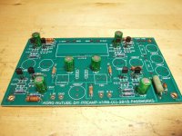
I used the green NICHICONs also in my KORG NUTUBE Preamp (not finished yet). Why? Because they sounded very good in the M2X. 😀
Greets
Dirk
Hello MEPER,
Hello M2X - builders,
I have used the NICHICON UES (green sleeve) bipolar caps in position C2
in my M2X with very good results.
At the moment I have a MUNDORF cap in there. Sounds also very good.
For me a very marginal difference in sound. Can't tell you which is better.
I used the green NICHICONs also in my KORG NUTUBE Preamp (not finished yet). Why? Because they sounded very good in the M2X. 😀
Greets
Dirk
Attachments
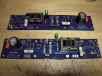
One specific Nichicon capacitor is called for in the M2x Bill Of Materials (and also on the official M2x schematics). It goes into position "C2".
Another specific Nichicon capacitor is called for, in all five of the M2x daughter cards' Bill Of Materials and on their schematics. Download the .zip archive file from post #1 of this thread, and have a look for yourself.
edit- you can also see these Nichicon capacitors in the color photos attached to post #2 of this thread. Let's try to link to that specific image:
C2 is on the M2x main board, and the other Nichicon is on the Tucson daughter board at far left. You can see that, besides the Nichicon, Tucson includes a second electrolytic capacitor, made by Illinois Capacitor. It is Mouser part number 598-477CKE050M .
~
Last edited:
M2X experience
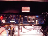
I am still working on the EDCOR shielding covers. I made them of copper (1mm).
Inside is now MU-metal foil (0.1 mm). I have electrical contact between inside
MU foil and outside copper.
I need to make a bracket for the covers over the EDCORs.
I will be surprised if it was worth the effort? I will report back.
What I can say: the M2X sounds very very good with the parts from
Mark Johnsons and 6L6s buildguide / bom.
Everything else are experiments!
Greets
Dirk
Attachments
- Home
- Amplifiers
- Pass Labs
- The diyAudio First Watt M2x