I am pretty sure there is no such thing as a variac.
It is like a 2x4 stretcher, something you send a newbie off to find.
My brother might have had one decades ago.
Probably easier to find someone that will admit to buying a Bee gees album that finding someone to admit that they own a variac 🙂
If the bulb went out on the bulb tester, then a variac will not gain much.
I did check the offset with the bulb tester hooked up just to make sure it was not way out of wack. That is simple prudence imo.
Oh, and you will never get a proper measurement on bias with a dimbulb in place. It will show faults, but what you are calling prudence is false confidence. with the M2 it wont matter because of optocoupler, but your measurement of bias or offset with dimbulb in place will never be right.
I dont worry about offset at this stage, as it doesnt matter. You do need to watch bias on other first watt amps while adjusting offset, F5 is a prime example.
Last edited:
So how important is it to have a Variac? Many talk about it like it is a given that everyone has one.
Yes, many here do speak of them, own them and make good use of them. For beginners, (or anyone) a dimbulb is a cheap easy way to find faults without damage. But you cant measure bias with one , which isnt important with M2 if all is well....Multimeters should be monitoring this. Offset isnt important before speakers are hooked up, you wont burn anything up but bias too high sure can.
With other Firstwatt amps where bias is set, they will save the day if you pots are not zeroed correctly, or the wrong way (full on) like if installed backwards.
F5 is an amp where I found it very useful. With it, bias changes with one pot, but so does offset. And the other way around as well. With variac, power can be brought up, while monitoring bias, which with F5 is see sawed back and forth along with offset. You can get crazy high offset, and turning it down can affect bias. I see sawed while upping voltage, making sure bias didnt go too high.
You can also keep an eye on the resistors and how hot they are getting as voltage goes up, or if anything begins to sizzle. Using one to test ANY power supply is a great idea as well, as I pointed out.
You can get a variac for reasonable money, but the dimbulb will serve you well in detecting problems before damage occurs. You wont need a 2 X 4 stretcher as far as I know. Some here might be surprised at the large volume of music and lyrics that were written by Andy Gibb for all sorts of other performers as well. Rest assured, many many experienced builders here own and use variacs.
variacs for sale - Google Search
Russellc
Last edited:
@Russellc
I seem to have pulled your chain, I being pretty much entirely ironic.
didn't mean to offend.
I seem to have pulled your chain, I being pretty much entirely ironic.
didn't mean to offend.
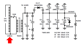
A variac was an essential, integral component of my Soft Recovery Diode test jig, for the article in Linear Audio magazine.
I bought mine from a local store, but Amazon sells the very same unit: (sales link)
_
I bought mine from a local store, but Amazon sells the very same unit: (sales link)
_
Attachments
@Russellc
I seem to have pulled your chain, I being pretty much entirely ironic.
didn't mean to offend.
Not at all. Just want to make sure folks here asking questions get straight answers. Your response made variacs sound like unicorns is all. Very common, very useful items. Some are very expensive, no real need for that. They can be very reasonable for the purposes needed here.
Russellc
First a GREAT BIG THANK YOU to all the support and help - I completed the M2 which is now playing music! YEAH. There is one item of note though. One of the channel bias was zeroed without problem. The other has RV1 turned all the way down to 0 and the reading on the DDM goes no lower than 13 mV. Is this acceptable? Is this where I should consider the 3. WARNING: BLASPHEMOUS HERESY! DO NOT READ THIS! from post #3? If so, should I do it to both channels to be consistent or just the one without ability to reach zero?
Last edited:
I'm getting close to finishing my build (still waiting on a few parts) is there a post or thread about biasing and testing this amp, I have never done this before and there are over 1200 posts to search through.
Thanks for any help.
Thanks for any help.
I'm getting close to finishing my build (still waiting on a few parts) is there a post or thread about biasing and testing this amp, I have never done this before and there are over 1200 posts to search through.
Thanks for any help.
Scroll back to post 1209, someone asked how to set up their amp.
Discussion continues from several sources.
Bias is automatic.
Once heatsinks are warm, adjust offset. Check again on next power up.
As mentioned, post 1209/1210 have good info.
Once heatsinks are warm, adjust offset. Check again on next power up.
As mentioned, post 1209/1210 have good info.
Hi,
If I am reading at the speaker output posts and am able to dial RV1 easily to get a DDM reading of zero on one channel, but with RV1 dialed all the way down on the other channel can only reach about 13 mV, what would be the best next step?
-Ses
If I am reading at the speaker output posts and am able to dial RV1 easily to get a DDM reading of zero on one channel, but with RV1 dialed all the way down on the other channel can only reach about 13 mV, what would be the best next step?
-Ses
Pass DIY Addict
Joined 2000
Paid Member
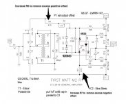
My M2 sits at about 20mV or so. If you REALLY want to get it to zero (which is difficult- adding or removing the lid changes things) here is a diagram that someone posted a while ago. As Zen said, this adjustment won't make any practical difference at your levels of offset.
Attachments
Is there an optimal stand—off height for mounting the boards, or just whatever gives enough clearance while accommodating the FETS? Thanks
Hi 6L6, i am not sure C2 could be used Tantalum polar type or Polypropylene or bipolar electrostic type get better sound result ?
Pass DIY Addict
Joined 2000
Paid Member
Is there an optimal stand—off height for mounting the boards, or just whatever gives enough clearance while accommodating the FETS? Thanks
Optimal comes with two constraints: long enough not to ground the component tails on the sinks and short enough to still reach to mosfet legs 😀
Generally 7-8mm works well. I have found 5mm to be a bit short to work with.
For Female-to-Female standoffs between motherboard and daughterboard, I used the ones called out in row 27 of the Bill Of Materials (Excel spreadsheet). Mouser P/N 534-24431
For Male-to-Female standoffs between heatsink and motherboard, I used the ones called out in row 28 of the BOM. Mouser P/N 855-R30-3000702
You can bend the leads of your MOSFETs and then measure how far they stick up from a mounting surface such as a heatsink. Don't forget to subtract off the PCB thickness and a little more, to ensure the lead pokes out a wee bit beyond the surface of the board. Voila that's your standoff height. Do or don't ignore the thickness of the Keratherm pad, however your engineering judgement and good taste guides you.
Hi,
question regarding the M2X build (- maybe better in another forum - please advise if this needs to be in another forum).
I used the deluxe chassis from the diyaudio store. I would like to convert it and add a power switch to the front. I am looking for advice on; Switch types (including any minimum necessary power ratings to watch out for), The wiring changes that have to happen from current setup with back power entry switch module, And finally, if anyone has experience here, anything with integrated blue LED to match my other equipment.
Thanks
Hi,
question regarding the M2X build (- maybe better in another forum - please advise if this needs to be in another forum).
I used the deluxe chassis from the diyaudio store. I would like to convert it and add a power switch to the front. I am looking for advice on; Switch types (including any minimum necessary power ratings to watch out for), The wiring changes that have to happen from current setup with back power entry switch module, And finally, if anyone has experience here, anything with integrated blue LED to match my other equipment.
Thanks
I bought this one from Ebay
25mm Latching Push Button Power Switch Stainless Steel w/ Blue LED Waterproof 845832018157 | eBay
I do not recommend it, it is a piece of junk. I wanted a nice big push button. I am know leaning towards a rocker switch - time will tell...
gwolfman liked a switch in the Mesmerize B1 thread
Mezmerize B1 Buffer Preamp
post #302.
I think he used the 3A version though.
I would click the link on the product page for the 82 series switch and filter for 240V/250V.
I suggest using a switch with at least twice the amp and voltage rating. If you are in the USA, you can use a single pole and put the switch inline with the hot wire from the mains. The fuse should (always) be between the power inlet and the switch. Just run the hot wire from the fuse/inlet up to the switch, and then back to the power supply.
If you are in a 240V are, you need a 2 pole switch, and should switch both wires.
You can switch both wires if you want in the USA for 115V, dunno about code elsewhere.
The LED on most switches will need its own low voltage supply (often 12V). If you get a switch with a 24V led, you can remove the led from one of the power rails, and run a patch wire to the LED in the switch, or simply move the LED to the chassis front, and not use the switches LED. You will probably have to experiment with resistor values to get the right brightness.
I used a piece of fiber optic, and put it in a boot over an LED in the power supply, and route the cable to the chassis front.
-Josh
Thanks for the advice on the offset. I am cycling through the daughter boards at the moment to see which on I like the best. Just to keep you engaged in the story, I was a bit underwhelmed by the amp during first run. Then switched the daughter board and was grinning like a five year old. My wife stated, "It is so real I've got chills." I have gotten stuck on the second of four completed daughter boards. I will report out on all four I built once I have tried them all.
As for the front panel switch wiring, understanding that I will be drilling out the front aluminum plate myself and do not need the blue LED, is there a recommended circular toggle for the M2X which is appropriate?
As for the front panel switch wiring, understanding that I will be drilling out the front aluminum plate myself and do not need the blue LED, is there a recommended circular toggle for the M2X which is appropriate?
Sesquipedalio,
I’m looking forward to reading about your observations. I’m running Tea-Bags M2C and my system sounds great. I have the M2x boards and will be building them in the future, but it is nice to read about the effect on the sound the daughter boards have. The modular design is such a great idea.
I’m looking forward to reading about your observations. I’m running Tea-Bags M2C and my system sounds great. I have the M2x boards and will be building them in the future, but it is nice to read about the effect on the sound the daughter boards have. The modular design is such a great idea.
- Home
- Amplifiers
- Pass Labs
- The diyAudio First Watt M2x