Test PSU without amp channels attached, connect one amp board, test and adjust, disconnect that one, connect the other, test and adjust, if all ok, try them both and listen to beautiful music.
It's a but more complex than that, but the important thing to understand is "hook it all up and hope the smoke stays in at initial power-up" is not the best plan, and any incremental steps are useful. 🙂
It's a but more complex than that, but the important thing to understand is "hook it all up and hope the smoke stays in at initial power-up" is not the best plan, and any incremental steps are useful. 🙂
Rafa -The universal PSU works ad fits great. I'd like one a bit smaller with a few revisions, mainly simplifications.
I built my PS from scratch. I purchased a large chunk of heavy un-plated fiberglass
US Stock 1x Epoxy Glass Fiber Resin Clad Plate Sheets PCB Board 3 x 200 x 250mm | eBay
I just drilled holes, glued the caps on with a small dab of silicone, and wired it up point to point using 14ga wire removed from some standard Romex. A word of warning though, you need a proper soldering gun for this (mine is 450W), or you will melt things. You don't save much space over the DIY store board, but you get to use it more efficiently for your specific needs. Eight 35mm caps occupy alot of space.
I started redesigning the PS because I want to change to discrete diodes. I use square rectifiers that bolt onto the chassis. Mine are bolted to some scrap aluminum and they get warm enough that they have to be substantially de-rated.
Boards of this size are very expensive to have made (in the $100.00's). So I am debating buying DIYAudio boards vs. making my own. The traces are so heavy, that it can easily be laid out with a sharpie, and not get into all the hassle of transfers and printers.
I am leaning towards making my own since there are other considerations.
The C60 thermistors are the wrong part. I found a nice thread started my Mark after I noticed mine are barely warm. My opinion is that the thermistor should be bypassed with a relay, so the board should be able to accommodate a method for detecting when the caps are charged.
I am also leaning toward putting the PS in it's own box so it can be used for other amp projects. This requires some flexibility if I want to add output snubbers and the like. I would probably also add some regulated low voltage circuits to the the box to get rid of my wall warts. The store boards are very flexible, but they are chunky because of their squareness, and can "only" hold 8 caps - I would like to experiment with using a 5th cap on each rail. I read an interesting thread form a guy that was using big motor start caps in the final stage to handle transients. Not relevant to an M2, but worth testing the concept on other potential amps.
Pass DIY Addict
Joined 2000
Paid Member
I was talking to somebody about that quite recently and yes, it does make a difference, and yes, having the wires face front (away from circuitry) seems to be the best orientation.
While I haven't tried this yet (my last few amps have had an external PSU), there may also be some mileage in using a brass (non magnetic) bolt for the transformer rather than a steel one. It might help reduce magnetic radiation in close proximity to that sensitive edcore transformer.
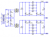
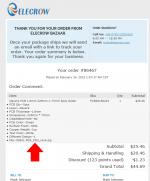
I built an M2x in a "Class A amplifier" chassis with BIG heatsinks, which I bought from eBay. The box was not very deep (front to back) so I laid out a custom PCB to fit standard First Watt power supply circuit, into a wide-but-not-deep area of the chassis floor. My board came out approx 23cm X 8cm. Circuit is shown in Figure 1 below. Receipt from purchasing five of these PCBs is shown in Figure 2 below. Please note: I only paid USD 45 to get five of the boards (!).
It uses off-board bridge rectifiers in the beefy GBPC package, bolted to the chassis floor. Connections between the bridges and the PCB are 1/4" FastOn blades, just like the ones on the M2x amplifier boards.
You can see from the receipt that my PCB uses "only" 1 ounce copper (35 um thick). But the traces are wide and I am very comfortable with the resulting current density J. [J = Current / (width * thickness)]. The PCB fab I used, Elecrow, only increases their price by 15% to 20% when you order double thick 2-ounce copper, so an extra double safe PCB, with wide AND thick traces (belt and suspenders) wouldn't be super expensive. However their quoted leadtimes do increase a bit for not-1-ounce orders and I WAS IN A HURRY. As most DIYers are, I imagine.
Executive summary: M2x power supply PCBs need not cost hundreds of dollars. Mine didn't, mine cost only $45 for five boards, and here is proof.
_
Attachments
Test PSU without amp channels attached, connect one amp board, test and adjust, disconnect that one, connect the other, test and adjust, if all ok, try them both and listen to beautiful music.
It's a but more complex than that, but the important thing to understand is "hook it all up and hope the smoke stays in at initial power-up" is not the best plan, and any incremental steps are useful. 🙂
In addition to what 6L6 suggests, I would also use a dim bulb tester. It saved my on my last build.
Plug for Teabag, his power supply boards are the bomb in my humble view. Fits wide range of caps, simplified resistors, led pads, super plain and simple and very thick heavy duty.
Russellc
Russellc
I used 2 Cap-Mx boards in my amp. You could use 1 and have a lot of room in the 4U 300mm chassis.
Testing Methodology for M2X Amplifier
Sorry for my inexperience. I am learning a lot and am very thankful for everyone's kind patience and help - with which I hope to be grinning ear to ear soon 😀
Thank you. Based on that, I developed the following, more detailed steps. Perhaps you can fill in gaps/corrections if you could, please?Test PSU without amp channels attached, connect one amp board, test and adjust, disconnect that one, connect the other, test and adjust, if all ok, try them both and listen to beautiful music.
- Wire AC Mains switch to ground and through block/thermistors to the toroidal primaries - Attach AC power to switch, turn on, and test using DMM set to AC on toroidal secondaries for proper (18V)
- Power down and wire toroidal secondaries (blue/green pair 1 -> PSU Diode AC1A/AC1B and blue/green pair 2 -> PSU Diode AC2A/AC2B). I have an assumption I want to check with this wiring. As long as the winding pairs stay together, as it is AC, it does not matter whether the blue or green goes to AC1A or AC1B or vice versa, correct?
- Power up and test both the diode arrays, with DMM set for DC voltage, with red/black to V+1/V-1 and V+2/V-2 to check DC voltages are correctly appearing on output of diode boards
- Power down and connect V+1/V-1 to D+1/V-1 on PSU board and V+2/V-2 to PSU board D+2/V-2 respectively
- Power up and set DMM do DC and re-verify DC voltages are found V+/V- on output blocks on PSU
- Assuming all is good with power to this point, power down and connect, one channel at a time:
- PSU V+, V-, and GND to M2 amp board VPOS, VNEG, & both GND.P points.
- RCA jack center to M2 board INPUT and RCA outer barrel to M2 board GND.I
- Speaker channel red to M2 OUTPUT and black to M2 GND.O or PSU ground for potentially less hum?
- Before powering up to test a channel, and here is another assumption I would like to check, turn the M2 board RV1 potentiometer to the HIGHEST resistance (approx 5K).
- Power up, connect the DMM to some test points and adjust the RV1 pot to get desired reading. I am not sure of the test points/target values, but believe Mark Johnson is addressing this in post #748. I believe I am supposed to:
- "insert shorting plugs to RCA" (Not sure what those are or how to do it properly).
- "Connect a dummy load resistor rated for at least 25 watts..." but how and where exactly to connect it, I am unclear. I also do not shop on ebay and I am not sure I have one or how to make one, if I could - or somehow [safely] test/do without?
- Place the DDM to DC volts and span the speaker posts measuring for zero volts while dialing "the potentiometer RV1 until the DC voltage across the loudspeaker posts is zero." Repeating at least two more times after +1 hour amp warm ups.
- Repeat for both channels and then hook up speakers to hopefully blow my mind, not my amp!
Sorry for my inexperience. I am learning a lot and am very thankful for everyone's kind patience and help - with which I hope to be grinning ear to ear soon 😀
Last edited by a moderator:
1) Be careful, an open transformer can supply a TON of current.
2) Yes, if the secondaries are properly paired, which can be determined with a simple continuity test, they can be attached to whatever input you desire on the bridges, but you've got to be consistent on both primaries/bridges. If you get them "inside out" you'll blow fuses
3) Yes. This number will be pretty high as you'll be testing a large transformer under no load
4) Yes
5) Yes
6)
.1 Yes
.2 Yes
.3 Speaker ground may be quieter at one of those locations, you've got to test and see. Start with it attached to the amp PCB
7) Nope. Leave it where it is, which is 1/2 way, as supplied by factory.
8) RV1 will adjust the DC offset on the speaker outputs.
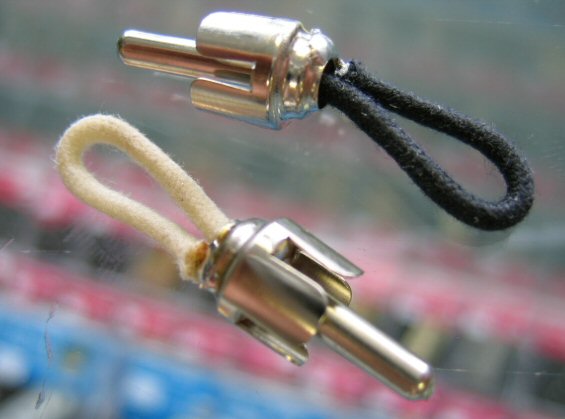
.1 Get some RCA males (like on the ends of cables) and electrically connect the outer ring to the pin, which will then make the input + connect to ground, shorting it (the input) to ground. See photo.
.2 Across the speaker jacks. Having the dummy load is not strictly necessary.
.3 Yes
9) Yes.
2) Yes, if the secondaries are properly paired, which can be determined with a simple continuity test, they can be attached to whatever input you desire on the bridges, but you've got to be consistent on both primaries/bridges. If you get them "inside out" you'll blow fuses
3) Yes. This number will be pretty high as you'll be testing a large transformer under no load
4) Yes
5) Yes
6)
.1 Yes
.2 Yes
.3 Speaker ground may be quieter at one of those locations, you've got to test and see. Start with it attached to the amp PCB
7) Nope. Leave it where it is, which is 1/2 way, as supplied by factory.
8) RV1 will adjust the DC offset on the speaker outputs.
.1 Get some RCA males (like on the ends of cables) and electrically connect the outer ring to the pin, which will then make the input + connect to ground, shorting it (the input) to ground. See photo.
.2 Across the speaker jacks. Having the dummy load is not strictly necessary.
.3 Yes
9) Yes.
Last edited:
I noticed the kind addition of the comment from BRN to, "In addition to what 6L6 suggests, I would also use a dim bulb tester. It saved my on my last build." After reviewing some online resources, it looks like I have the parts to make one. The question I have is when and how many time I should use it? Only for the PSU portion above (steps 1-5) or multiple times? What are best practices here?
I would use the dim bulb tester at each step when adding another component to your build. Once you know there is no short you can remove it and test the voltage and make any adjustments.
@ Mark
Thanks for the tip. I didn't bother with them because they look sketchy, and they do not offer 3oz copper. The board I was looking for is much bigger, and is designed to carry a second single rail PS, the diodes/sinks, and circuitry for a micro-controller.
I did a quick compare to EasyEda, they would make your boards for $14.00 + shipping. Might be worth checking out, never used them myself but they are trying to get into the market.
I will definitely consider them if I ever need a small board with 1oz Cu.
Most of the vendors I found that had good reps and get recommended wanted in the neighborhood of $5.00/sq" plus a one time set up fee. One actually quoted me over $1300.00 for 5 boards.
Not relevant, I redesigned things to use smaller boards and will etch the PS board with some acid and a sharpie for under $20.00.
Toroidal transformers have about 1/10 the EMI that conventional transformers do. They are very quiet with respect to EMI, especially if they are sized properly. And like all EMI, it goes down with the square of the distance. This is why toroids are used so often in devices that require special EMI/EFI compliance. I would be more worried about EMI from the Edcore than EMI from the toroid.
EMI is a bigger concern if the transformer is bolted to something like a steel chassis that can carry the charge around.
A current will develop on the bolt. Assuming you use a metal chassis, that current goes straight to ground. Considering the bolt is made from random junk in the recycling pot, I doubt it generates enough current to affect noise on the ground plane. If you are worried about it, use a stainless bolt and save the cash over a brass bolt. Or better yet, strap it to the chassis with plastic zip ties.
Thanks for the tip. I didn't bother with them because they look sketchy, and they do not offer 3oz copper. The board I was looking for is much bigger, and is designed to carry a second single rail PS, the diodes/sinks, and circuitry for a micro-controller.
I did a quick compare to EasyEda, they would make your boards for $14.00 + shipping. Might be worth checking out, never used them myself but they are trying to get into the market.
I will definitely consider them if I ever need a small board with 1oz Cu.
Most of the vendors I found that had good reps and get recommended wanted in the neighborhood of $5.00/sq" plus a one time set up fee. One actually quoted me over $1300.00 for 5 boards.
Not relevant, I redesigned things to use smaller boards and will etch the PS board with some acid and a sharpie for under $20.00.
While I haven't tried this yet (my last few amps have had an external PSU), there may also be some mileage in using a brass (non magnetic) bolt for the transformer rather than a steel one. It might help reduce magnetic radiation in close proximity to that sensitive edcore transformer.
Toroidal transformers have about 1/10 the EMI that conventional transformers do. They are very quiet with respect to EMI, especially if they are sized properly. And like all EMI, it goes down with the square of the distance. This is why toroids are used so often in devices that require special EMI/EFI compliance. I would be more worried about EMI from the Edcore than EMI from the toroid.
EMI is a bigger concern if the transformer is bolted to something like a steel chassis that can carry the charge around.
A current will develop on the bolt. Assuming you use a metal chassis, that current goes straight to ground. Considering the bolt is made from random junk in the recycling pot, I doubt it generates enough current to affect noise on the ground plane. If you are worried about it, use a stainless bolt and save the cash over a brass bolt. Or better yet, strap it to the chassis with plastic zip ties.
A member asks:
The answers are:
1. No, the M2x main PCB and the Norwood daughter PCB (and four other daughter PCBs too!), are sold by the diyAudio Store, not by me. These are blank, empty boards; they're not kits. link here
2. No, I don't have any Edcor transformers to sell.
3. 24VAC x 2 transformer is not going to work for the M2x. One transformer that I do recommend is the Antek AS-3218. It is 2 x 18VAC, with 300VA rating. Antek link
Please avoid using Private Messages to ask about diyAudio Store products, as it completely negates the whole point of the Forum. You want to access the combined knowledge and wisdom of the entire membership of diyAudio, which PM cannot do.
- Do you still have M2 main board and Norwood daughter for sale?
- I want to get a pair of of transformer for this amp (Edcor pc600), do you have this thing sell ?
- My external AC supply is 24VAC x 2 (250W) per channel, can it be used for this AMP ?
The answers are:
1. No, the M2x main PCB and the Norwood daughter PCB (and four other daughter PCBs too!), are sold by the diyAudio Store, not by me. These are blank, empty boards; they're not kits. link here
2. No, I don't have any Edcor transformers to sell.
3. 24VAC x 2 transformer is not going to work for the M2x. One transformer that I do recommend is the Antek AS-3218. It is 2 x 18VAC, with 300VA rating. Antek link
Please avoid using Private Messages to ask about diyAudio Store products, as it completely negates the whole point of the Forum. You want to access the combined knowledge and wisdom of the entire membership of diyAudio, which PM cannot do.
A member asks:
- Do you still have M2 main board and Norwood daughter for sale?
- I want to get a pair of of transformer for this amp (Edcor pc600), do you have this thing sell ?
- My external AC supply is 24VAC x 2 (250W) per channel, can it be used for this AMP ?
The answers are:
1. No, the M2x main PCB and the Norwood daughter PCB (and four other daughter PCBs too!), are sold by the diyAudio Store, not by me. These are blank, empty boards; they're not kits. link here
2. No, I don't have any Edcor transformers to sell.
3. 24VAC x 2 transformer is not going to work for the M2x. One transformer that I do recommend is the Antek AS-3218. It is 2 x 18VAC, with 300VA rating. Antek link
Please avoid using Private Messages to ask about diyAudio Store products, as it completely negates th whole point of the Forum. You want to access the combined knowledge and wisdom of the entire membership of diyAudio, which PM cannot do.
Add to the list the AS-4218 with the antistatic shield which has also been used with success.
AS-4218 - 400VA 18V Transformer - AnTek Products Corp
I use the 500VA, 18 + 18 volt Antek with no no shield in several of my First Watt clones with success as well. Commercial First Watt amps use 300VA, most here likely know that.
Russellc
Russellc
What brand toroid transformer use in pass amps
From Nelson Himself, aside from Plitron transformers he has suggested the Antek As-3218, which has also been suggested by Mark, and has shielding. If it’s good enough for him then it should be good enough for us. But using a larger VA transformer isn’t a bad thing either.
http://www.antekinc.com/content/AS-3218.pdf
Not sure what the sound of this amp compare to general class A , this is using transformer as interstage coupling. I mean transformer couple how the sound performance?
The transformer is wired as an auto former and used for voltage gain, it is not interstage coupling.
The sound of this amp has all the advantages of "general class A" and the added wonderful of magnetics in the signal path. I really like it.
The sound of this amp has all the advantages of "general class A" and the added wonderful of magnetics in the signal path. I really like it.
- Home
- Amplifiers
- Pass Labs
- The diyAudio First Watt M2x