Thanks mark. Yeh ive heard so much conflicting info. In the end i think we just have to make it and listen
Tungstenaudio,
Nice work with the new dual-mono power supply setup; how much capacitance did you use for the filter capacitors on each of the PCBs?
Nice work with the new dual-mono power supply setup; how much capacitance did you use for the filter capacitors on each of the PCBs?
I have been thinking about a valve buffer / linestage for my VFET amp (P-type), and have collected parts needed to build one. The form factor for that amp is more accommodating to larger components in the FE.
The M2x could certainly sound great with a tube FE, but the board size and electrical interface for the buffer cards would make it more difficult to implement. There are a lot of other options for M2x buffer designs. I happen to be soldering a new pair of cards that are a cascode version of the Ishikawa design. I have already tried an HV opamp version of Tucson, which I described earlier.
The M2x could certainly sound great with a tube FE, but the board size and electrical interface for the buffer cards would make it more difficult to implement. There are a lot of other options for M2x buffer designs. I happen to be soldering a new pair of cards that are a cascode version of the Ishikawa design. I have already tried an HV opamp version of Tucson, which I described earlier.
Someone started a Forum thread last year, to organize a group project to design and build a vacuum tube front end card for the VFET amps. I don't know whether that group is still actively working on the idea, or not.
I followed that thread for as long as it was active. There were a couple interesting ideas and one circuit proposal.
A couple ideas suggested low-ish voltage pentodes such as the 3S4 or 3V4. I haven’t seen circuits with these tubes, as they date from early car audio and the pre-interwebs era.
A more detailed proposal included a dual-triode as a differential amplifier with a transistor current source on the tail. It needed both a high voltage B+ supply and a –15V supply for the current source. Looked interesting, but a lot of work that needs a custom PCB.
A different thread had a more interesting circuit that used a 6V6 in a fairly straightforward linestage. That looks doable as a simple turret board construction. I have parts for that. The power supply still needs an external chassis. I have parts and transformers for that as well. The supply can be a point to point construction, completely enclosed for safety.
Obviously this is all more advanced than what some folks were hoping for. That is why the thread went silent many months ago. I have it as one of several projects that I’m multi-tasking.
I finished building a pair of
https://www.diyaudio.com/community/...dule-for-yarra-m2x-pete-millet-design.373155/
I might install and test this coming weekend.
https://www.diyaudio.com/community/...dule-for-yarra-m2x-pete-millet-design.373155/
I might install and test this coming weekend.
When I start making progress on a VFET amp tube front end, I will start a new thread.
I remembered that I was also looking at an EF86 linestage with modest gain. This is also doable on a small turret board.
I remembered that I was also looking at an EF86 linestage with modest gain. This is also doable on a small turret board.
Quick question to the community. Since I use the D-Sub connectors on my daughter cards, it takes me all of 30 seconds to swap them out. I forgot about the thermistor surge protectors and blew a fuse by turning on the amp without letting it cool much.
What is the recommended delay between turning off and turning on the M2x? Thanks in advance.....
What is the recommended delay between turning off and turning on the M2x? Thanks in advance.....
Depends on which inrush current limiter part you've installed. For the one I've installed in my M2x (here's more than you'd ever possibly want to know) , I pause for 2 x 45 = 90 seconds during a "hot restart". See datasheet below, 2nd line from the bottom. >89 seconds works well for my M2x and I haven't blown fuses.
_
_
Attachments
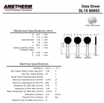
Thanks Mark, I'm using CL60 type, I forgot which brand.Depends on which inrush current limiter part you've installed. For the one I've installed in my M2x (here's more than you'd ever possibly want to know) , I pause for 2 x 45 = 90 seconds during a "hot restart". See datasheet below, 2nd line from the bottom. >89 seconds works well for my M2x and I haven't blown fuses.
_
My M2X, which has been performing beautifully for a couple years, had a failure tonight. One channel made a thump in the speaker then nothing. The other channel is still working fine. I checked the bad channel's speaker output and it's showing -24.8 VDC. i don't see any scorched parts. Q1 is hot and Q2 is cold while the board is powered up with +/-26 VDC. Any pointers for diagnostic steps would be greatly appreciated.
I always start with confirming if its the amp, or the speakers, or any upstream devices....preamp etc. I run a tube preamp so i'm used to swapping things around to find the bad component. In my case usually a tube. You could try swapping your input cards and go from there.My M2X, which has been performing beautifully for a couple years, had a failure tonight. One channel made a thump in the speaker then nothing. The other channel is still working fine. I checked the bad channel's speaker output and it's showing -24.8 VDC. i don't see any scorched parts. Q1 is hot and Q2 is cold while the board is powered up with +/-26 VDC. Any pointers for diagnostic steps would be greatly appreciated.

I always start with confirming if its the amp, or the speakers, or any upstream devices....preamp etc. I run a tube preamp so i'm used to swapping things around to find the bad component. In my case usually a tube. You could try swapping your input cards and go from there.
Thanks for the suggestions. I removed the input board and the speaker terminals still have -24.8 VDC.
if you have -24.8 VDC at speaker output it's probably because you have a shorted output mosfetMy M2X, which has been performing beautifully for a couple years, had a failure tonight. One channel made a thump in the speaker then nothing. The other channel is still working fine. I checked the bad channel's speaker output and it's showing -24.8 VDC. i don't see any scorched parts. Q1 is hot and Q2 is cold while the board is powered up with +/-26 VDC. Any pointers for diagnostic steps would be greatly appreciated.
You got -24.8VDC at the speakers, Q2 is cold, Q2 is fed with postive voltage. My bet, Q2 is fried or is not turning on.My M2X, which has been performing beautifully for a couple years, had a failure tonight. One channel made a thump in the speaker then nothing. The other channel is still working fine. I checked the bad channel's speaker output and it's showing -24.8 VDC. i don't see any scorched parts. Q1 is hot and Q2 is cold while the board is powered up with +/-26 VDC. Any pointers for diagnostic steps would be greatly appreciated.
- Home
- Amplifiers
- Pass Labs
- The diyAudio First Watt M2x