The packaging concept I am working on is based on the use of 4 heat sinks arranged in a tall square column. This will hold the amp boards.
TomServo's "Tower of Class-A Power"? 😀
Thanks but I am still unsure what the recommendation to use C0 is.It is your amplifier. Try it with and without C0.
The second thing:
Ichikawa RV1 should be set at middle . Unfortunately, I have bought it with the RV1 mounted and I don't know how to check if it's at the middle of value. DMM shows me: 9R, 6R and 15R between legs. Is the only option .desoldering the pot?
From post #3, on the first page of this thread:
5. Capacitor “C0” is not present in the original M2 amplifier by Nelson Pass. The M2 owner’s manual explains that this makes it easier for tube preamps to drive an M2. However C0 does perform a useful function: together with input resistor R1, it filters (removes) unwanted radio frequency interference. The transformer’s HF rolloff helps too. I suggest that if you’re absolutely certain you’ll never drive M2X with a tube preamp, never ever ever, consider soldering C0 into the amplifier board. C0 is a NP0/C0G ceramic capacitor, 50 volts, 220 pF. Of course you can cut it out later if you change your mind.
From post #3, on the first page of this thread:
Unfortunately, my English is too weak to understand the meaning of this part of the guide.
(too many "never, ever"😉)
So please clarify:
M2X + Tube preamp = mount C0 or not mount C0.
Thanks but I am still unsure what the recommendation to use C0 is.
The second thing:
Ichikawa RV1 should be set at middle . Unfortunately, I have bought it with the RV1 mounted and I don't know how to check if it's at the middle of value. DMM shows me: 9R, 6R and 15R between legs. Is the only option .desoldering the pot?
Most of them click when they reach a stop, one way or the other, turn the pot until it reaches the stop, turn it back counting your turns, when it clicks again, divide by 2, and turn it back.......
JT
Unless you have a distortion analyzer or real time spectral analysis, it will be difficult to find a good setting for RV1. It’s not something that can be reliably set by ear. Perhaps it would be better to remove the trim pot, especially for initial setting of the amp.
Been running my M2X for over 6 months now, it has become the main amp in my system along with the Elekit Pre, they replaced a Copland CSA29 integrated which is no slouch.
Thanks Papa.
Thanks Papa.
Ampboards are almost ready 🙂
I'll wash and clean tomorrow.
Ischikawa and Mountain View are ready too. Can I run and check my daughter's cards without ampboards and without the regulated power supply? I only have a power supply for M2x and DMM. I saw a nicely described diagram for Norwood, can someone add it to other cards?


I'll wash and clean tomorrow.
Ischikawa and Mountain View are ready too. Can I run and check my daughter's cards without ampboards and without the regulated power supply? I only have a power supply for M2x and DMM. I saw a nicely described diagram for Norwood, can someone add it to other cards?
darr
What did you use to shield your Edcor's with? Please also post lots of pics as you box things up.
Regards,
Don
What did you use to shield your Edcor's with? Please also post lots of pics as you box things up.
Regards,
Don
I have copper tape so I shielded the transformer before soldering. It certainly won't hurt it.
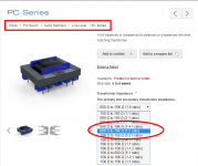
I'm not entirely sure of what Edcor transformer series is being used in the M2X. I'm looking at the Edcor website and I believe it is the "TPC Matcher Series" (just not mounted on the Edcor-supplied PC board) or is it the the "PC Series" which comes unmounted?
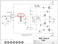
I ask because if I look at the M2X schematic vs. the schematics on Edcor's website, the pin numbers/phase relationships are presented differently.
The TPC Matcher Series shows Pins 1 and 7 being in phase, while the PC Series shows Pins 1 and 5 being in phase. I note that on the M2X schematic, NO phase "dots" are indicated for the transformer - so I'm confused.
Can somebody please help? Thanks!
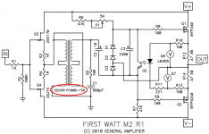
Besides this M2x thread, there is another resource here on diyAudio. It's a thread about the commercial product M2 which was sold by FirstWatt. Nelson Pass created the thread and attached his M2 schematic to post #1 of that thread.
Official M2 schematic
Nelson Pass's M2 schematic is the first attachment below. I've included some other attachments, hoping to make clear which Edcor transformer is used in the M2 and the M2x.
_
Official M2 schematic
Nelson Pass's M2 schematic is the first attachment below. I've included some other attachments, hoping to make clear which Edcor transformer is used in the M2 and the M2x.
_
Attachments

- Home
- Amplifiers
- Pass Labs
- The diyAudio First Watt M2x