
Waiting
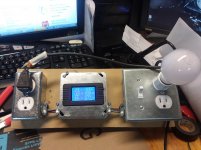
Waiting on the Edcors and some power supply stuff, I had the chance to make this today:
The reading are of the J2... It's wired, so to measure off both sides, the left at full mains and both controlled by the switch.
Waiting on the Edcors and some power supply stuff, I had the chance to make this today:
The reading are of the J2... It's wired, so to measure off both sides, the left at full mains and both controlled by the switch.
Attachments
Last edited:
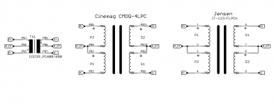
I think I remember seeing a set of M2 PCBs a couple years ago, which were laid out in such a way that the builder had the option to install either the Edcor transformer (as here), or another transformer by Jensen, or a third transformer by Lundahl, or a fourth transformer by Cinemag. This provided the builder an opportunity to re-create the listening tests which Nelson Pass performed before finalizing and publicly releasing the M2: Which transformer gives the most pleasing results, to you ?
[schnipp]
Sorry that I don't remember who created and displayed those PCBs, or whether they were for sale, or what they cost. Laying out an option-rich amp channel PCB yourself would be a viable alternative; it's a large roomy board with very few components and loads of space between them. You could even put the transformer on is own daughter card, if you wished; that would transfer the pinout-scramble from the amp channel PCB to the daughter card, and it would also enable builders to fabricate a mu-metal shield box which completely enclosed the transformer including its bottom side. With daughter cards, swapping transformers would take only 5 minutes; you could audition all four different possibilities in less than an hour.
You'd probably want to locate the transformer's Zobel network (R5-C1 in the M2x schematic) on the daughter card. That way each transformer gets its own unique and optimum Zobel. You don't need to find a "compromise" Zobel that sorta works okay with all four transformers.
Mark, I'm 99% positive it was teabag and it was his F6 convertible you are thinking of here diyAudio - Tea-Bag a 1/4 way down the page there is the F6 convertible with the daughter cards for different transformers.
Hmm, that may be what I once saw, but I sure don't remember any white PCBs. M2 builders take note: enormous flexibility and multitudes of options are available to those who create their own PCB layouts.

An excellent demonstration of " ... that would transfer the pinout-scramble from the amp channel PCB to the daughter card"
Almost got it right. See post #266
And Papa got to exercise his preference for nickel alloy in the F6 design. Not sure what part the transformer plays or if it is overwhelmed by other circuit topology differences, but I definitely prefer the sound of my F6 build to my M2x build (with any of the input modules). M2x is just a bit too hard (steely?) for my taste

cinemag?
Anyone know what type and model cinemag would be used in place of the Edcors for the M2X?
Had not heard of these before reading the last few posts-
Tx
Anyone know what type and model cinemag would be used in place of the Edcors for the M2X?
Had not heard of these before reading the last few posts-
Tx
And Papa got to exercise his preference for nickel alloy in the F6 design. Not sure what part the transformer plays or if it is overwhelmed by other circuit topology differences, but I definitely prefer the sound of my F6 build to my M2x build (with any of the input modules). M2x is just a bit too hard (steely?) for my taste
That's how I felt about the F5T that the highs were a little forward for my ears and brain. Nobody hears the same, but mine have had years of race cars and reports from firearms, so I get fatigued fast if the highs are up front.
I hope that's not true of the M2 as I'm building them right now lol.
Anyone know what type and model cinemag would be used in place of the Edcors for the M2X?
Had not heard of these before reading the last few posts-
Tx
see in first post of Babelfish M25/Sissy SIT tips and tricks thread
though , there are all classic repeaters (so called 600R:600R with CT in primary) , resulting in slightly lower gain than you are getting with 600R:15K
repeaters, as connected in mentioned amps, are giving 4V/V , while with 600R:15K in M2 - gain is 6V/V
M2 dimensions question
I have looked and looked, but it seems that dimensional info on the original M2 are not easily found.
I am interested in knowing the height of this amp, and the depth of the case, front to back.
Curious about those heat sinks.
Thanks,
M
I have looked and looked, but it seems that dimensional info on the original M2 are not easily found.
I am interested in knowing the height of this amp, and the depth of the case, front to back.
Curious about those heat sinks.
Thanks,
M
Since the original M2 was a commercial product, sold by the commercial business "First Watt", that might be a good place to start. Another idea: google search for audio reviews of the First Watt M2; perhaps one or more reviewers measured the external dimensions of its chassis, and printed those measurements in the review.
Well, I didn't want to bug First Watt with a question like that.
But I did find a page on this site that showed the following dimensions:
480mm wide by 385mm deep by 143mm high.
Turned out, I was googling Pass M2 dimensions, and what I should have been using was First Watt M2 dimensions.
Anyway, found what I was after: the original was somewhere between a 3U and 4U case height, and the heatsinks went 385mm deep.
Thanks!
M
I built my M2x into a chassis that was 2.5U high by 400mm deep. No problem with power dissipation, as the M2 is not particularly power hungry. The important part is to keep some physical separation between the power transformer and the Edcor signal transformers. Hence a 400mm deep chassis. Those Edors are susceptible to hum pickup.
That's how I felt about the F5T that the highs were a little forward for my ears and brain. Nobody hears the same, but mine have had years of race cars and reports from firearms, so I get fatigued fast if the highs are up front.
I hope that's not true of the M2 as I'm building them right now lol.
Built the F6 as my first Pass design amp. Thought it was pretty good, then upped the bias zeners to 5.6V and biased the outputs until the devices themselves ran about 60 degrees C. Nirvana.
Built the M2x out of curiosity and respect for Mark J's Noir HPA. The M2x sounds more like the F6 at lower bias settings but still different and more analytical. The various input modules did change things in subtle ways. I feel I owe it to the amp to try Mark's suggestion of an OPA1611 on the Tucson board. I absolutely love the OPA1612 (stereo version) in my Whammy HPA.
I also suspect the M2x automatic bias circuit is a bit conservative. My M2x output devices are running about 50 - 52 degrees C. My next step will be to see if there is some way to readjust that circuit for just that little bit more bias that helped the F6.
The closest I can come in describing the differences between the two amps is that the F6 is more like a B1 Korg preamp and the M2x more like a FET based preamp (my reference for that is a Harmon Kardon hk 725). It's not just the H2 level, possibly the proportion of H2 to H3 as well. It surprised me that the F6/B1K combo was not "too much of a good thing" and I prefer it to the M2x/B1K combo.
Tungsten: Thanks for that experience.
I am going to probably build this one a bit differently than is what is typically done.
In my case, I am building a pair of amps, as I am going to use them to replace the amps I am currently using for biamping.
The packaging concept I am working on is based on the use of 4 heat sinks arranged in a tall square column. This will hold the amp boards.
A separate power supply will be used to feed these, one supply per channel. I can locate this away from the amp column and so deal with the noise (I hope). This drives an all horn system, so I do have to be careful about the noise.
I would kind of like to have the Edcore end at the top of the column, but that would mean moving the RCA inputs to the top. Visually, not as clean as I would like to see, though. Since the power supplies would be located away, I may be able to get away with this. Easy enough to change- the column comprised of the four heatsinks would have end plates fitted with one end doing power in, the other, signal in. I could swap ends, I suppose.
Still working out the details, but the more I pursue this concept, the more I like it for my purposes.
-M
Since you won't be using the pre-drilled UMS heatsinks from Modushop / diyAudio Store, you might as well create a new PCB layout for the amp channel boards, which matches your particular heatsinks. Then you could locate the Edcor transformer on the PCB in whatever position and orientation you think is optimum, and you could leave plenty of empty space around the Edcor to install a mu-metal shield which completely surrounds it and blocks mains hum.
Hi🙂
I'm currently mounting amp board. Unfortunately, my English is too weak to understand the meaning of this part of the guide.
(too many "never, ever"😉)
So please clarify:
M2X + Tube preamp = mount C0 or not mount C0.
Should there be a jumper at C0?
I'm currently mounting amp board. Unfortunately, my English is too weak to understand the meaning of this part of the guide.
(too many "never, ever"😉)
So please clarify:
M2X + Tube preamp = mount C0 or not mount C0.
Should there be a jumper at C0?
C0 is mounting for tube pre?No jumper at C0. Leave that open, or try a 470 pF Silver mica capacitor.
- Home
- Amplifiers
- Pass Labs
- The diyAudio First Watt M2x