Fully Complementary Mosfet Grounded Source Class-H
SMD's are fun to work with.😀
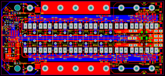
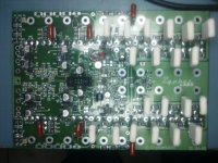
PCB measures 18 X 8 cms and designed for 1.5kW@2ohms
IRFP240/9240 at output && IRFP140/9140 at switching
SMD's are fun to work with.😀
PCB measures 18 X 8 cms and designed for 1.5kW@2ohms
IRFP240/9240 at output && IRFP140/9140 at switching
Attachments
Last edited:
hi workhorse
greetings do you sell kits or amplifiers
thanking you
andrew lebon
hi,
I only design.......!!!😉
Power Level
What a robust design is that?
How many KW i can get with that Amplifier?
Nice...
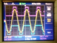
1. 3-Step Class-H waveforms
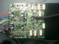
2. 3-Step SMD version using pairs MJW21195/95
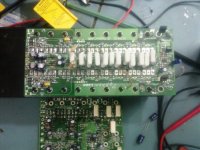
4. 2-Step Mosfet SMD version using IRFP240/9240 & IRFP140/9140 complementary output and Switching
😉
What a robust design is that?
How many KW i can get with that Amplifier?
Nice...
What a robust design is that?
How many KW i can get with that Amplifier?
Nice...
Yeah.......
The output power is expandable from 2kw@2ohms to 4kw easily by adding more devices and beefing up the power supply.😉
Power
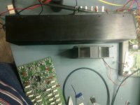
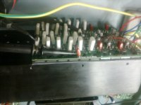
That is REAL development of Class-H with some REAL pictures, Also a High Power with Small Size.
Nice WORK .... 🙂
Thanks
Yeah.......
The output power is expandable from 2kw@2ohms to 4kw easily by adding more devices and beefing up the power supply.😉
That is REAL development of Class-H with some REAL pictures, Also a High Power with Small Size.
Nice WORK .... 🙂
Thanks
Very nice work Workhorse, congratulations!
can you tell us something about the levels choice for Vcc steps and the results of your measurements on these beasts?
Regards.
can you tell us something about the levels choice for Vcc steps and the results of your measurements on these beasts?
Regards.
Very nice work Workhorse, congratulations!
can you tell us something about the levels choice for Vcc steps and the results of your measurements on these beasts?
Regards.
Hi
If you opt for 2 step i would recommend asymmetrical steps because the music has very high peak to average ratio. for example lower tier voltage =70V an upper tier voltage= 40V so total voltage will be 70+40=110V this gives best results in 2 step class-H, as most of the time music swing will be on its average level only goes to high tier during peaks.
In 3-Step, the rails are best chosen as same voltage difference steps like 55, 110, 165 in 3 steps as used in my prototypes. 3-step is actually good for highpower amps for subwoofer applications and they also facilitate the use of 250V VCE devices at rails +/-165VDC the upper most tier. Efficiency of 3 step is much higher than class-AB and surely cuts waste heat and cost.
I am getting less than 0.1% THD@1khz at full power from these prototypes. power is limited to 2KW@2ohms for 4 pairs of MJW21196/95 pairs.
Thnxz
Hey. Workhorse
Can u share your schematics here 🙄

Hi Gold,
Djk is right the actual efficiency with Musical waveform is much different as I already said, with pure sinewave its very much different thing, because the Musical Content features lots of High amplitude peaks in comparision with normal average program material and this is where the Class-H/G amp seeks its advantage and proving more efficiency....
Thanks DJK for valuable comments....
K a n w a r
That may true:
Exploding the Efficiency Myth of Class D Amplifiers | ECN: Electronic Component News
http://www.newelectronics.co.uk/articles/22076/p21-22.pdf
Nothing more efficient than using headphones. Your big heatsink showing its efficiency problems😀 ,nice work for that big one, but smaller is better (for me of course).
Last edited:
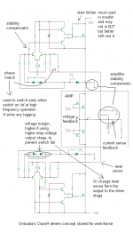
I am going to share my drivers here, may be too late but could be used as reference. I have many schematic but nothing of them could be used at my mosfets amplifier, so I make my self drivers. Do not judge from its simple, it is powerful driver.
Attachments
Last edited:
That may true:
Exploding the Efficiency Myth of Class D Amplifiers | ECN: Electronic Component News
http://www.newelectronics.co.uk/articles/22076/p21-22.pdf
Nothing more efficient than using headphones. Your big Heatsink showing its efficiency problems😀 ,nice work for that big one, but smaller is better (for me of course).
Class-H is much efficient than Class-AB, but don't compare it with Class-D which is totally different thing.
Having made Class-AB/H/G/D, Class-D gave me highest of efficiency and reduced Heatsink size.😉
- Home
- Amplifiers
- Solid State
- The Class - H Amplifier