Decided to finish it? Well, if he decides to change his mind...he had my PM for an offer to buy it. 😀
Al r.
Al r.
my niece showed interest when we met, so i gave him as b.d. gift. if he doesn't want to continue or if and when i get hold of the supply i mentioned before, will pm you guys. tkx.
sometimes i wonder why no one is doing cdm0 replica, now we have laser this, super alloy that, the precision can only get better, and in my opinion swing-arm mechanism rules.
Peter, apologies if this has been answered before, but what would you say are the important characteristics of an ideal transformer for Shigaclone?
I'm asking because Hammond don't appear to make transformers with 230V primaries... At least none that I could find for sale in England 🙁. The closest I could find to a Hammond was this rather unconvincing thing: CAMDEN ELECTRONICS - CTFC100-12. And here is its datasheet.
An alternative would be to order a custom toroid from toroidy.pl with all the bells and whistles, and hope it will not sound worse than the original boombox trafo... 😀
The general agreement seems to be that Hammond E-I types work better in this application than toroids, so I was wondering if it is because of Hammond's dual bobbin winding? 😕Then the E-I core would have the advantage of having less capacitative coupling between windings. I'm guessing, in a toroid an electrostatic shield between windings would help to some degree in this case...?
And if the advantage of EI is simply its better noise rejection then a toroid + choke could do equally well, I think?... (although I'm not really sure what kind of choke would it have to be - I just read this somewhere 😛)
I find E-I types to work slightly better here than dual split bobbin like the one I'm using in a DAC, however I don't know why.
I never tried toroids though.
I never tried toroids though.
Thanks Peter, I've ordered a custom 300VA toroid, but will also try the E-I I linked earlier as it's cheap, so why not 😉 That will give me a total of 3 transformers to choose from (including the original JVC), surely at least one will be half-decent...
I plan to put together a PS as per Peter's schematic, but then try a few different caps and diodes. I've ordered samples of 4 different types of diodes from ON Semi, who knows, maybe I'll discover something worthwhile.
I can't find any 47/50 BG N for sale, despite having searched what seems like 3/4 of the entire internet looking for it... So I'm gonna try a few different BG STD and BG FK values in this position instead.
Also, I couldn't get any BG STD 1000/25, so I'll use STD 1000/50 instead.
Peter, what do you make your cap-rolling sockets of?
This is what I use: http://www.diyaudio.com/forums/equipment-tools/3981-useful-tools-techniques-5.html#post53407 , but recently couldn't find any at the local store.
I modify the original display board next: it's trimmed, and what (needed) traces have been cut, they are now replaced with hookup wire. Unnecessary components in top layer are also removed. I also trim plastic display board housing. It can be removed by taking out 2 screws and desoldering IR receiver, LED and display pins.
There are 5 connection points to the switches:
2 common for all buttons
S stop
P play
B back skip
F forward skip
The buttons are spread 0.7" apart. The display is attached to wooden frame with a single, isolated head, screw. There is additional TOC switch mounted on a side (normally closed type).
Hi Peter
Could you please identify the buttons in image from the top row, the second from left
First from left with orange wire, second with grey wire, both soldered to the flat cable connector, and
Fourth and fifth with grey wires soldered to empty remaining holes.
Thanks
JC
Last edited:
Ok, I've found the raw unit SF-P10 16 pin sanyo phillips alba transport on an auction site. If I've gotten the correct item, I'm in for this build. Hopefully I got the right thing?
Russellc
Russellc
Ok, I've found the raw unit SF-P10 16 pin sanyo phillips alba transport on an auction site. If I've gotten the correct item, I'm in for this build. Hopefully I got the right thing?
Russellc
The item was #280556406688 on e bay. It looks like the right thing, but it doesnt appear to have everything that Peter's picture shows. Also, I guess I dont have the clamp or the display parts. Are they available or should/could I build it without? I should have thought of this before purchasing, but it was only 20 bucks or so.....
Thanks for any responses,
Russellc
Well, crap game over! (I think) I just noticed it doesnt have the board underneath like Peter's pic shows. I guess that finishes it? Nuts.
Russellc
Russellc
Well, crap game over! (I think) I just noticed it doesnt have the board underneath like Peter's pic shows. I guess that finishes it? Nuts.
Russellc
Not yet
http://salestores.com/jvcrce02.html
Last edited:
Hi Peter
Could you please identify the buttons in image from the top row, the second from left
First from left with orange wire, second with grey wire, both soldered to the flat cable connector, and
Fourth and fifth with grey wires soldered to empty remaining holes.
The buttons from left are skip back, skip forward, stop, play, and the gray wire attached to pad with #2 is a common wire.
I thought the RC EZ 32 wasnt the same as RC EZ 31? I found a RC EZ 31 online for 89.99. What's the story with the R 32 version?
russellc
This is what I use: http://www.diyaudio.com/forums/equipment-tools/3981-useful-tools-techniques-5.html#post53407 , but recently couldn't find any at the local store.
For anyone interested in making their own capacitor sockets, I found that PC fan connectors work brilliantly:
An externally hosted image should be here but it was not working when we last tested it.
Just cut them off any old fan, or look up "Multi Fan Connector" in Google Shopping - you should be able to get a nice multi-fan connector for less than £3 off eBay (inc. shipping) and it will yield four sockets.
They are the perfect size for 3-pin voltage regulators, TO-220 packaging diodes (such as MUR860 or MSR860), small capacitors and many, many other things. The holes are actually wide enough to accept most bigger capacitor leads too - I even managed to fit in a BG STD 1000/50 without effort (although the leads have to be long enough).
For bigger size capacitors though, I recommend this:
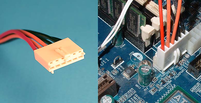
It is an "ATX Aux" power connector - obsolete now, but older PC power supplies should still have it (a Chieftec HPC-300 I found at the bottom of my cupboard did).
It accepts comfortably and securely virtually any conceivable device that has wire leads.
Installing sockets makes comparing stuff so easy. In the past, I have not done much comparing (pretty much as little as I could get away with), mainly because it was too much time/effort to solder stuff over and over. But with sockets, it's truly a 10-second job: power off, take item 1 out, plug item 2 in, power on. Brilliant.
You only have to keep reminding yourself not to swap things too often or you'll lose track of the changes 😉
Edit:
Here's how I did it:
An externally hosted image should be here but it was not working when we last tested it.
I marked the negative pole on all sockets so that I wouldn't have to check polarity every time. On the voltage regulator socket I marked pin 1 instead. I also wrote the regulator's pin-out on the heatsink, just in case 😉
Last edited:
WOW! Perfect,I have a rcez-31 on the way found it on amazon.com 90.00 us.
Thanks for all your help!!!!!!
Fred
Thanks for all your help!!!!!!
Fred
Hi ALL!!!!!
Peter,Thanks for sharing all your time and skills to help some of us less efficient folks along!
Peter,Thanks for sharing all your time and skills to help some of us less efficient folks along!
- Status
- Not open for further replies.
- Home
- More Vendors...
- Audio Sector
- The CD Transport