I am delusional !!
I just commented on the input stage , not the OPS.
Sansui , nikko , most other Japanese designs used some form of a 3 stage differential in the 70's/80's.
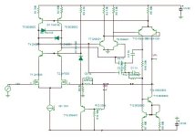
1st - Jfet LTP + cascode with R/C lag and double diodes for clip control.
2nd - standard LTP , sometimes with compensation.
3rd - either a standard VAS or another LTP with minor miller comp.
Most fed a standard EF3 and then applied lead compensation at NFB.
Nice results - Rupop !!
OS
I just commented on the input stage , not the OPS.
Sansui , nikko , most other Japanese designs used some form of a 3 stage differential in the 70's/80's.
1st - Jfet LTP + cascode with R/C lag and double diodes for clip control.
2nd - standard LTP , sometimes with compensation.
3rd - either a standard VAS or another LTP with minor miller comp.
Most fed a standard EF3 and then applied lead compensation at NFB.
Nice results - Rupop !!
OS

H
HAYK
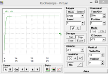
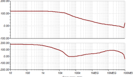
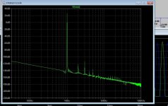
To get very high slew rate, I used the other phase as output because the capacitors on the output were limiting it. Look the fabulous OLG. The saturation slew rate reaches 1000v/us. The distortion is 0.0002% for now.
Attachments
1000V/us ?? What OPS could do that. Simulation is one thing , real world is another. Present day BJT EFx OPS's have a low 300V/us limit.
This was tested (Slewmaster).
.0002 is unclean blasphemy - wolverine does .00002 ! 😉
Dirty ol' spookyamp does .0002 ??
OS
This was tested (Slewmaster).
.0002 is unclean blasphemy - wolverine does .00002 ! 😉
Dirty ol' spookyamp does .0002 ??
OS
Actually , besides there are some RF 5G amps that can do 1000V/us.
"suckout cap" on the EF3 was how we got the EF3 to do over 300. Base Cob of the outputs vs. the that cap (suckout).
OS
"suckout cap" on the EF3 was how we got the EF3 to do over 300. Base Cob of the outputs vs. the that cap (suckout).
OS
H
HAYK
It will drive in open loop OPS that purposely generates 0.3%. See post 23 and 26. And when closed loop with 50db NFB I am satisfied with 0.001%. My ears don't hear THD bellow 0.1%.
H
HAYK
What is the distortion of your loudspeakers?1000V/us ?? What OPS could do that. Simulation is one thing , real world is another. Present day BJT EFx OPS's have a low 300V/us limit.
This was tested (Slewmaster).
.0002 is unclean blasphemy - wolverine does .00002 ! 😉
Dirty ol' spookyamp does .0002 ??
OS
I know , it's just mental masterbation .....
You ask the question = many percent !
PS - I'm satisfied with .005 @ 4R , that's my criteria. Reliability "grace under pressure" , is so much more important.
Then there is clipping behavior , we all get over ambitious.
OS
You ask the question = many percent !
PS - I'm satisfied with .005 @ 4R , that's my criteria. Reliability "grace under pressure" , is so much more important.
Then there is clipping behavior , we all get over ambitious.
OS
So for now the front-end and OPS are sharing the same fuse. I think performance is to be gained from giving the front-end its own set of fuses, such that no fuses are shared with the OPS. It seems most distortion comes from the half-wave decoupling currents dropping voltages over the PSU impedance shared by front-end and OPS. What is your opinion on this matter? Would that be safe?
Furthermore I have a transformer four sets of both 38VAC and 76VAC center-tapped. Currently im using the 38VAC's to get +&-52VDC. I could use the 76VAC's to get +&-100VDC as dedicated front-end supplies. Said front end supplies would need a separate pcb as it wont fit on the current one. Im still considering whether this redesign would be worth it.
Please let me know what you think.
Cheers,
Ruben
For frontends I would use extra transformers or windings with voltage regulators and add RC filters 10 ohms / >=470uF + film caps.
Reasons: No hum, no dependence from line fluctuations
Reasons: No hum, no dependence from line fluctuations
For the first PCB version im sticking with a single set of supplies and fuses. The fuses itself measure about 18mOhm which should only causes negligent distortion when soldered.
Removing Ground Lift:
Im trying to descide on the ground-lift scheme. Only Input:

Or input and feedback:

My conclusion in neither as I was already planning to use this scheme off the amplifier board. A ground lifter on the input caused problems with the Green Comet Amplifier. One earth loop breaker per channel should be safer and make the input ground lifter redundant.

Removing Ground Lift:
Im trying to descide on the ground-lift scheme. Only Input:
Or input and feedback:
My conclusion in neither as I was already planning to use this scheme off the amplifier board. A ground lifter on the input caused problems with the Green Comet Amplifier. One earth loop breaker per channel should be safer and make the input ground lifter redundant.
Last edited:
H
HAYK
Hifisonic who advises to use power Bridge diode for circuit break, himself do not use in his amplifiers. Just a pair of 1n4007 is sufficient specially for a prototype.
H
HAYK
I searched to buy C3503/A1381, Ali do not have the A1381. On eBay is pricey. Nearby vendors have C3502, I bought a pair for $0.4 and the A1380 is $3 from Ali for 10 pieces.
I have A1360 which has 200Mhz ft VS 150Mhz but on simulator it has lower gain. In fact the NFB@20khz is 104db if fall to 91db with 1360.
Where did you find the lsk489? Unknown on Ali.
I have A1360 which has 200Mhz ft VS 150Mhz but on simulator it has lower gain. In fact the NFB@20khz is 104db if fall to 91db with 1360.
Where did you find the lsk489? Unknown on Ali.
Last edited by a moderator:
Mouser has stock of KSA1381/KSC3503
Send asuslover a PM:
https://www.diyaudio.com/community/threads/some-components-for-sale.314633/
Send asuslover a PM:
https://www.diyaudio.com/community/threads/some-components-for-sale.314633/

Tried Digikey? I got LSK489's by contacting Linear Systems. They hooked me up with IB Fluck germany. However it must be available on digikey now.I searched to buy C3503/A1381, Ali do not have the A1381. On eBay is pricey. Nearby vendors have C3502, I bought a pair for $0.4 and the A1380 is $3 from Ali for 10 pieces.
I have A1360 which has 200Mhz ft VS 150Mhz but on simulator it has lower gain. In fact the NFB@20khz is 104db if fall to 91db with 1360.
Where did you find the lsk489? Unknown on Ali.
Nice , thanks to you ... I also have a crazy high OLG design. I did it with just 2 stages by loading it with current mirrors.
Most amps just have 10db extra at 20K. Wolverine has about 30 , (62db/20K). My new one has 72. 10db more goes a long way.
.5PPM at 20k.
It was cool your design came along as I was redesigning a similar topology. I didn't use your exact design , I did not need 90db and
the 3'rd stage.
Your layout looks real nice , I see you are HF decoupling (.1uf) your big electro's underneath with SMD. I originally thought to do this on my through-hole
output board , opted to keep it ALL through-hole. Plenty of SMD's on the IPS's , which I intend to keep ALL SMD
I should get some fancy new 3D PCB layout software !
OS
Attachments
Actually , besides there are some RF 5G amps that can do 1000V/us.
"suckout cap" on the EF3 was how we got the EF3 to do over 300. Base Cob of the outputs vs. the that cap (suckout).
OS
I wonder how the cheap and plentiful TPA6120A2 Class AB headphone chip amp achieves 1500V/usec. Only good for +/-15v though but still amazing.
- Home
- Amplifiers
- Solid State
- The Catharsis Music Magnifier, The Elusive Hexfet CFP from spice fantasy to PCB