H
HAYK
Dear HAYK,
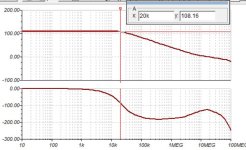
Your simulations dont close the nfb loop around the output stage so naturally the OL bandwidth is higher. It also makes your mod a different amp altogether. The output stage is just as characterising to the cathersis as the front-end. I suggest you start a new thread for your non global nfb amp.
Youre using different jfets, different models overall and no OPS causing your results to be different. IIts unclear what your gain and phase margins are. OL bandwidth is only meaningful when gain and phase margins are stated too. Nice work nonetheless.
Cheers,
Ruben
H
HAYK
The circuit will be used without global feedback, with 16db NFB and maximum NFB. In 2-3 days the board will be finished and I will test it as unity gain pre amp by reducing the output with 270k/10k, and a switch to compare with and without pre amp and adjust by ears to get an amplifying wire. Then I will add k1058/j164 as output stage with global feedback and listen to it daily until I finish my distorting output stage.
I adjust the stability by square wave shape. Lead capacitor can be added, as 5pF with the above MOSFETS.
I adjust the stability by square wave shape. Lead capacitor can be added, as 5pF with the above MOSFETS.
Why don’t you make your own thread for it? It’s a substantially different amp and it’s just clogging the discussion around OP’s amp now
Hi HAYK,
Your version is different enough to be your own. Straightout copying and using all same values i would regard as theft. So feel free to start your own thread. Lets end this discussion here as this only adds to offtopic content.
Much cheers,
Ruben
Your version is different enough to be your own. Straightout copying and using all same values i would regard as theft. So feel free to start your own thread. Lets end this discussion here as this only adds to offtopic content.
Much cheers,
Ruben
Finally testing of a second channel has begun. Ill construct one more and keep the first build as a testing mule which has some scars from deslodering.

With 50V rails the offset walks around a little but stays below 20mV. Not enough for me to go for coupling caps.
Im getting about 150W before clipping. Slewrate is just over 40V/us.
At 5kHz 100W into 4 ohms im maybe seeing 0.0001% THD. This is the difference between input and output of the catharsis. It remains hard to determine. I need a lower distortion source.
Bias is set to 250mA per mosfet and so it idles at about 53W per channel.
Hopefully with current component values it proves reliable too.
If indeed it does prove reliable im planning to design a more diy friendly PCB mkII. This should have larger feedback resistors, larger zobel resistors, no redundant component footprints, a little more spacing between components and clear testing points and indication. Maybe an input capacitor.
Also im yet to design the auxilary dc servo board.
So far so good.
Much cheers,
Ruben Pulles

Right,..show don't tell.
Today I got the source distortion a bit lower by playing with its gain. THD dropped below 0.001%.
These are measured from the negative input of the input differential pair of the catharsis. Voltage over the 4 ohm load was 22Vrms equating to 120W or so.
Including source distortion or not, these are good numbers for a power amp anyhow.
Stereo at last!

Finnally I got two channels tested and installed for the first stereo listening.
Obviously im affected by builders bias.
However,
the first thing that stood out was that ambient sounds seemed to surpass the speakers up down left and right more so than with my cyrus mission one.
This seemed really appearent when listening to Pretty by Puma Blue. (And his other latest singels)
Next I played William by Mount Kimby which sounded huge and holographic. Then 'Before I move off' also by mount kimby and I noticed how pinpoint the sparkly synthy sounds were. Meanwhile there is a certain ease to the sound. It sounds relaxed. Not in a rolled-off on top way but relaxed in a crystal clear way.
Unfortunately im still working out some earthloop hum in the left channel. I should have included input groundlift after all. The good thing is that either channel is deadsilent when the other is disconnected. The black earthlines positioned and twisted like this minimizes the hum for now. However hum will be tricky when everything is placed in a case.
Now lets hope I dont short anything so I can continue listening to the Catharsis.
Much cheers,
Ruben Pulles
Very nice , like your layout.
Your project is another example of why some of the DIYA "business interests" seem to be overly condescending.
We "the pitchfork villagers" ... have matched or exceeded their creations.
Yes , "Holographic" = a PPM amp.
OS
Your project is another example of why some of the DIYA "business interests" seem to be overly condescending.
We "the pitchfork villagers" ... have matched or exceeded their creations.
Yes , "Holographic" = a PPM amp.
OS
Congratulations! You have not only built the design, but made very complex frequency compensation work.
Ed
Ed
Congratulations! You have not only built the design, but made very complex frequency compensation work.
Ed
Thank you Ed!
However, i abbandoned the complex 2 pole transitional compensation (post#102) and went for just 2 pole compensation in the end like shown in post #111. Still feel a bit sore about 2ptc seeming to work at first but then blowing fuses not much later.
Cheers
Hi Cacull,How much noise on the output(s) are you getting right now?
My multimeter is seeing about 0.1mVrms on the noisier channel.
Earth now connects to the input to keep the loop small. But its only quiet with the transformer in the distance.
Now only with my ear on the tweeter I can barely makeout some buzz. Transformer inbetween the channels gives horrendous buzz and hum.
Bridging the channels could help perhaps but Ill leave that to another design where the OPS can handle double the current. Im already getting 170W into 4 ohm and I dont need the even harmonics to be cancelled out.
Cheers!
Ruben
- Home
- Amplifiers
- Solid State
- The Catharsis Music Magnifier, The Elusive Hexfet CFP from spice fantasy to PCB